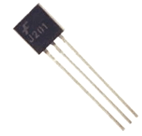
J201 Pinout, Datasheet, Equivalent, Specifications
 Dr. James Anderson
Published:December 21, 2023
The J201 JFET N-channel transistor stands out as a versatile electronic component designed primarily for general-purpose applications featuring low-level audio and high-impedance signal sources. Its unique properties make it an ideal choice for a variety of electronic circuits where maintaining signal integrity and achieving low noise operation is important.
Description of J201
J201 JFET N-channel transistor is a versatile component widely used in various electronic devices. Its main strength is its ability to work well with audio preamplifiers, making it excellent for boosting weak audio signals, such as those from microphones. This transistor operates with little extra noise to keep the amplified sound clear and faithful, making it ideal for applications such as guitar effects pedals.
But the J201 isn't just for audio. It is also useful in many other types of circuits. Its special talent is that it can boost weak signals without adding much extra noise. This is useful for things like sensor circuits that need to pick up sensitive signals. Also suitable for switching applications in electronic equipment.
In situations where you need components that operate at low power, J201 is the best choice. Useful in devices that operate on low voltage and current, such as battery-powered gadgets. Boost voltage efficiently while using just the right amount of power. This makes them a smart choice for electronic devices that require energy efficiency. Its properties also make it a reliable switch in some electronic circuits
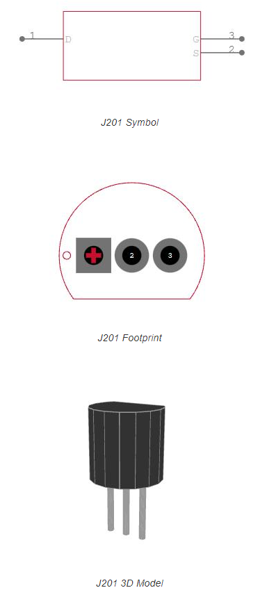
J201 Pinout
J201 is a junction field effect transistor (JFET) commonly used in electronic circuits due to its voltage control characteristics. Understanding the pin configuration is essential for proper integration into your circuit design.
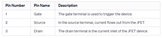
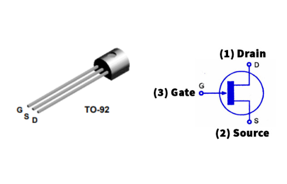
J201 Pin Configuration
Pin 1: Drain
The drain terminal is where the main current flows into J201. This serves as the connection point for the output current in the circuit. This is an important terminal for understanding transistor operation from a current control perspective.
Pin 2: Source
The source terminal is where the current exits J201. This is the point at which the transistor releases a controlled current into the circuit. To understand the output characteristics of a transistor, it is essential to understand the source terminal.
Pin 3: Gate
Gate terminal is the control terminal of J201. It regulates the flow of current between the drain and source terminals based on the applied voltage. The voltage at the gate terminal determines the conductivity of the JFET, making it an important factor for controlling the device in electronic applications.
Features of J201
JFET (junction field effect transistor)
J201 belongs to the JFET category, a type of transistor known for its voltage control characteristics and ability to regulate current flow.
N channel
J201 is an N-channel JFET, which indicates the use of negatively charged carriers (electrons) for current conduction between the drain and source terminals.
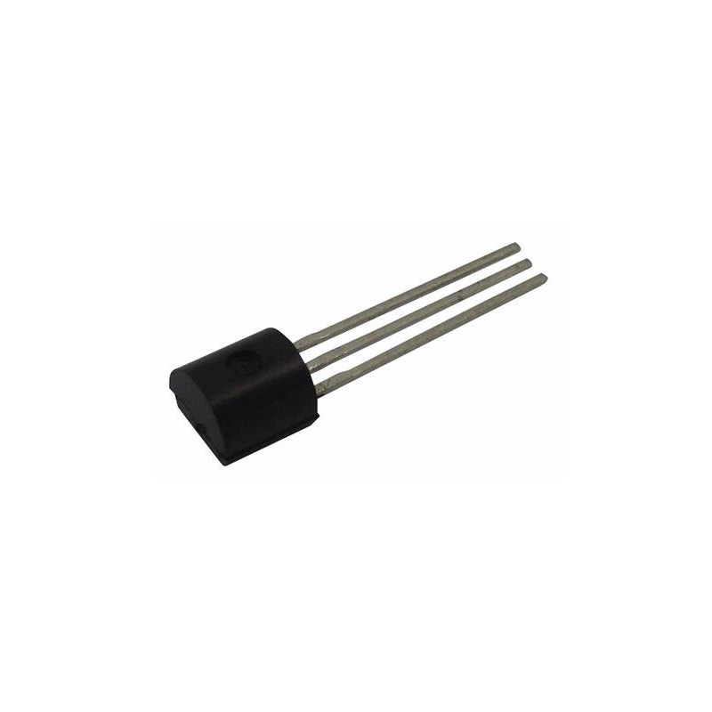
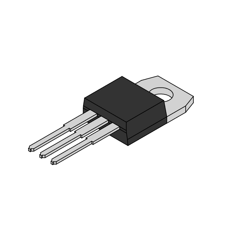
package
J201 is typically packaged in a TO-92 package, a widely used compact packaging style suitable for small signal transistors. This package facilitates integration into various electronic circuits.
low cutoff voltage
J201 is characterized by a low cutoff voltage. This means that it requires a relatively low voltage on the gate terminal to initiate the flow of current between the drain and source terminals.
High input impedance
One of the J201's notable features is its high input impedance. This means that the transistor imposes minimal loading on the preceding circuitry, making it suitable for applications where input signal preservation is important.
Very low noise
J201 is known for its very low noise characteristics. In applications such as audio amplification and sensor circuits, low noise is essential to maintain signal clarity and fidelity.
High gain
J201 transistors provide high gain and are effective in amplifying weak signals in a variety of applications. This feature is particularly advantageous in scenarios where signal amplification without significant distortion is required.
The combination of low cutoff voltage, high input impedance, very low noise, and high gain makes the J201 suitable for applications where accuracy and sensitivity are important. It is commonly used in audio circuits, sensor interfaces, and other applications where its specific characteristics contribute to optimal performance.
J201 Specifications
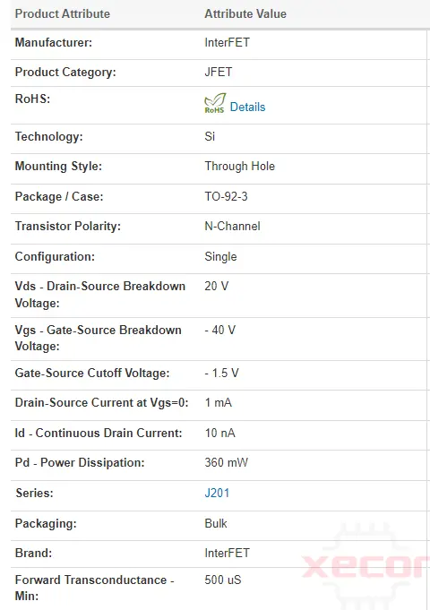
Absolute Maximum Ratings
- Voltage across Drain and Gate: VDG = 40 V
- Voltage from Gate to Source: VGS = -40 V
- Current flowing into the Gate: IGF = 50 mA
- Range of Junction Temperature for Operation and Storage: TJ, Tstg = -55 to +150 °C
J201 Equivalents/Alternatives
When replacing a transistor, it is important to consider factors such as voltage rating, current handling capability, and most importantly, pin configuration to ensure seamless integration into the intended circuit.
The 2SJ201 is a junction field effect transistor (JFET) similar to the J201. They share comparable properties and can often be used as replacements. However, it is important to note that specifications and pin configurations may differ, so check compatibility before replacing.
LJ2015-52:
LJ2015-52 is also equivalent to his J201. This transistor is designed to work similarly to his J201 and can be used for a variety of electronic applications. As with any substitution, it is important to check the pin configuration to ensure proper integration.
MMBFJ201 is a JFET transistor that can be used as a functional replacement for J201. It is important to review the datasheet for this component to ensure compatibility, especially regarding pin configuration.
CJ201NL is another equivalent that can be used in place of J201. As always, it is important to compare datasheets and check pin configurations before replacing to avoid discrepancies.
2N4338, 2N4339, 2N4340, 2N4341, 2N5458, 2N5459, 2N5457, NTE458:
These transistors are also listed as equivalent to J201. However, I would like to emphasize that the pin configuration may be different. Therefore, it is highly recommended to cross-reference the datasheet of the specific transistor being replaced to ensure accurate pin mapping.
J201 CAD model
Characteristics curves of J201 JFET
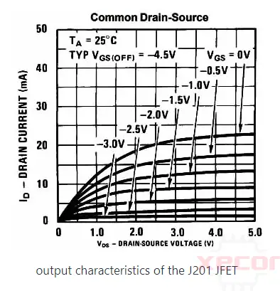
The graphs depict the output characteristics of the J201 JFET device, illustrating the relationship between drain current and drain-to-source voltage.
With a consistent cutoff voltage, variations in the gate-to-source voltage result in an escalation of the drain current. The drain current undergoes incremental growth, reaches a saturation point, and eventually exhibits an infinite trend.
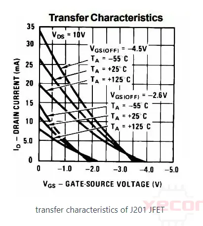
The illustration depicts the transfer characteristics of the J201 JFET, presenting a graph of drain current against gate-to-source voltage.
Maintaining constant drain-to-source voltage values and employing two distinct gate-to-source cutoff voltages, the drain current declines towards the negative range concerning the gate-to-source voltage.
Where to Use it & How to Use
The J201 component finds application in diverse scenarios involving the amplification of low-level signals. It proves particularly useful when there is a need to enhance a signal's gain substantially while simultaneously mitigating noise through effective filtration. Its versatility extends to applications in audio preamplifiers, microphone preamplifiers, and associated circuitry. Furthermore, the J201 can serve in the realm of infrared signal detection and amplification.
J201 Application
High gain, low noise amplifier:
J201 is suitable for applications where high gain and low noise are important and is ideal for delicate amplification tasks in electronic circuits.
Low current, low voltage battery powered amplifiers:
J201's low current and voltage requirements make it ideal for use in battery-powered amplifiers, contributing to energy efficiency and extended battery life.
Infrared detector amplifier:
J201 is employed in circuits designed to amplify signals from infrared detectors commonly used in remote controls, security systems, and other applications requiring infrared sensing.
Ultra-high input sensor circuit:
Applications that require ultra-high input sensitivity, such as certain sensor circuits, can utilize the J201 to accurately and efficiently amplify weak signals.
Audio preamp circuit:
J201 is commonly used in audio preamplifier circuits to boost weak audio signals from microphones or other sources before further amplification.
Audio amplifier stage:
Within an audio amplification system, J201 serves as a critical component in specific amplifier stages, contributing to overall signal processing and fidelity.
Laser detection and data amplification:
In laser detection systems, J201 serves to amplify the signal generated by the photodetector, contributing to accurate data amplification in laser-based applications.
Infrared detection and data amplification:
J201 can be used in parallel with infrared detectors to amplify the signal of infrared detection systems, such as those used in communication devices and motion sensors.
Buffer circuit:
J201 can be used in buffer circuits to isolate different sections of the circuit, prevent loading effects, and ensure signal integrity in electronic systems.
Boost circuit:
Considering its characteristics, J201 can be used as part of a circuit designed to boost voltage levels, making it valuable in applications where voltage amplification is required.
Low level audio amplifier circuit:
J201 is often used in low-level audio amplification circuits, contributing to the amplification of weak audio signals with minimal distortion.
How to Safely Long Run in a Circuit
To ensure enduring and dependable performance from the J201 FET transistor, it is advisable to limit the load to under 50mA. Avoid exceeding a gate-to-source voltage of -40V and a drain-to-gate voltage of 40V. Additionally, store and operate the transistor within the temperature range of -55 to +150 degrees Celsius.
J201 Datasheet
Download J201 Datasheet PDF.
2N5457 vs J201 vs 2N5458
When comparing the 2N5457, 2N5458, and 2N5459 JFETs, their performance is determined by more than just the model number. Rather, they are classified during manufacturing based on their pinch-off voltage (Vp), with approximate values of 1.5V, 2.5V, and 3.5V, respectively.
The choice depends on your application. A low Vp device like the 2N5457 may provide higher gain in the amplifier, while a high Vp device like the 2N5459 will tolerate hotter signals and noise-generating phaser voltage controlled resistors, etc. suitable for applications. There will be less distortion.
MPF102 is a replacement for 2N5458 and thus 2N5459, but J201 is in a different category as it has much lower Vp and Idss than 2N5457.
In summary, J201 and 2N5457 are recommended for amplifiers, and 2N5459, 2N5458, and MPF102 are recommended for phasers. Other FETs, such as J111 and PN4392, have lower resistance and higher current consumption, making them ideal for use as analog switches rather than amplification applications.
J112 vs J201
J112 and J201 are both junction field effect transistors (JFETs) with similar applications, but they differ in their electrical characteristics. Here's a comparison between J112 and J201:
1. Types of transistors:
J112 and J201 are both N-channel JFETs that use negatively charged carriers (electrons) to conduct current between the drain and source terminals.
2. Pin configuration:
J112 and J201 have different pin assignments. If you use pins in your circuit, make sure they are connected correctly according to the datasheet.
3. Transconductance (GM):
Transconductance measures a transistor's ability to amplify small signals and can be different for J112 and J201. Specific values vary depending on component manufacturer and grade.
4. Cutoff voltage (Vgs(off)):
The cutoff voltage, the voltage at which the transistor turns off, may be different for J112 and J201. This parameter is important for understanding the threshold voltage required for JFET operation.
5. Drain current (Idss):
The maximum drain current (Idss) when the gate is shorted to the source may be different between J112 and J201. This parameter is important for determining the transistor's operating conditions and current handling capabilities.
MPF102 vs J201
MPF102 and J201 are different N-channel JFETs, and MPF102 requires significantly more current than J201 for optimal operation. Tillman circuits designed for J201 may not be suitable for MPF102 as they may operate outside of the specified parameters and may cause problems such as attenuation. The main differences are in pinch-off voltage and current requirements, and when replacing transistors in electronic circuits, it is important to consider each transistor's unique characteristics.
Final Words
In conclusion, the J201 JFET N-channel transistor emerges as a versatile component, ideal for applications requiring high input impedance, low noise, and efficient signal amplification. Its influence extends from the delicate realm of audio preamplifiers to the broader realm of general purpose electronics, demonstrating its adaptability and reliability in a variety of electronic circuits.

FAQ
-
What is a J201 transistor?
The primary design focus of the J201 centers around catering to low-level audio and general-purpose applications, particularly those involving high-impedance signal sources.
-
What does a JFET transistor do?
Junction Field-Effect Transistors (JFETs) are semiconductor devices featuring three terminals. They find utility as electronically controlled switches or resistors and are also employed in the construction of amplifiers.
-
Can you replace JFET with MOSFET?
JFETs and MOSFETs are not necessarily interchangeable. JFETs exhibit a higher input impedance compared to MOSFETs, implying that they demand less current from the input source.

Still, need help? Contact Us: [email protected]