A1015 Transistor Datasheet, Equivalent, Pinout, Circuit & Uses
 Dr. James Anderson
Published:April 02, 2024
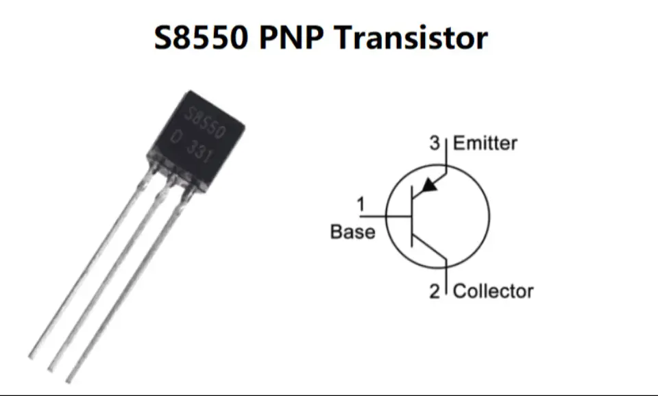
PNP (Positive-Negative-Positive) transistors are one of the two main types of bipolar junction transistors (BJTs). They play a crucial role in amplification and switching applications. The A1015 is a commonly used PNP bipolar junction transistor (BJT) in electronic circuits for various applications. In this article, we'll delve into the A1015 datasheet, pinout, circuit, equivalent, uses, and more details. Everything you need to know about this PNP transistor.

Description of A1015 Transistor
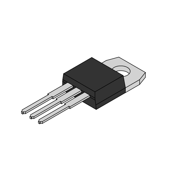
The A1015 is a general-purpose PNP transistor designed for low-power amplification and switching applications. It is housed in a TO-92 package, making it suitable for use in compact electronic devices. The transistor has a maximum collector current (Ic) of 150mA, making it suitable for low- to medium-current applications. The A1015 transistor is renowned for its reliability and versatility, particularly in applications requiring low power and voltage.
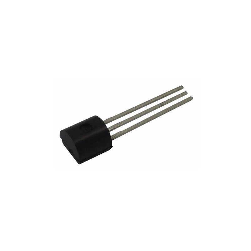
A1015 Pinout

A1015 Pin Diagram
A1015 Pin Configuration
| Pin No. | Pin Name | Description |
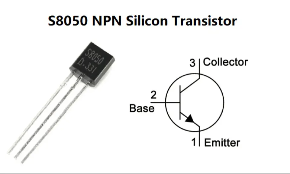
| 1 | Emitter | The emitter is for the external association of current. |
| 2 | Collector | The collector is for the current inward drive. It is related to the load. |
| 3 | Base | The base administers the biasing of the transistor. It vagaries the state of the transistor. |
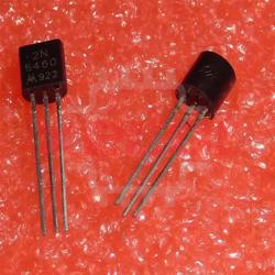
The A1015 transistor typically comes in a TO-92 package, which is a widely used package for small signal transistors. It has three pins, each serving a specific function:
- Emitter (E, Pin 1): The emitter is the pin through which the current enters the transistor. It is typically connected to the ground or the negative side of the circuit.
- Collector (C, Pin 2): In most circuit configurations, the collector is the pin that connects to the positive supply voltage. It is where the output current flows out of the transistor.
- Base (B, Pin 3): The base is the transistor's control pin. By applying a small current or voltage at the base, the transistor can be switched on or off, controlling the larger current flowing between the collector and emitter.
A1015 CAD Model

Features and Specifications
| Type | Parameter |
| Transistor Type | PNP |
| Maximum Collector Power Dissipation: Pc | 0.4watts |
| Maximum Collector-Emitter Voltage: Vceo | 50V |
| Maximum Collector Current: Ic | 150mA |
| Low Noise | 1dB |
| DC Current Gain: hfe | 70 ~ 400 |
| Collector-Base Voltage: Vcb | -50 V |
| Collector-Emitter Voltage: Vce | -50 V |
| Emitter-Base Voltage: Veb | -5 V |
| Maximum Collector Current: Ic max | -150 mA |
| Collector Emitter and Collector Base breakdown voltage | 50Vdc |
| Base Emitter Saturation Voltage | 1.1Vdc |
| Collector Emitter Saturation Voltage | 0.3Vdc |
| Base Emitter voltage | 1.45Vdc |
| Operating Temperature and Storage Temperature | -55℃ to +150℃ |
| Transition Frequency: ft | 80 MHz |
| Package / Case | TO-92 |
| Complementary Transistor | 2SC1815 |
Absolute Maximum Ratings (Ta = 25°C)

Electrical Characteristics (Ta = 25°C)

A1015 Equivalent/Alternative
The A1015 transistor has several replacements that offer similar functionality and performance. Some of these equivalents/replacements include:
| Equivalent Parts | Description | Application |
| NTE290A | General-purpose PNP transistor | Various electronic circuits |
| 2SA495 | Low-frequency PNP transistor | Audio amplification, low-frequency applications |
| 2SA561 | High-voltage PNP transistor | High-voltage switching applications |
| 2SA564A | High-gain PNP transistor | Applications requiring high gain |
| 2SA573 | Low-power PNP transistor | Battery-powered applications |
| 2SA675 | High-speed PNP transistor | High-frequency applications |
| 2SA705 | High-current PNP transistor | Applications requiring high current |
| 2SA999 | High-power PNP transistor | Power amplification applications |
| KSA1015 | General-purpose PNP transistor | Wide range of electronic circuits |
| KTA1015 | High-frequency PNP transistor | High-frequency applications |
| KTA1266 | High-power PNP transistor | Power amplification applications |
| KT3108A | Low-noise PNP transistor | Low-noise amplification applications |
| BC212 | General-purpose PNP transistor | Wide range of electronic circuits |
| BC257 | Low-power PNP transistor | Battery-powered applications |
| BC307 | High-speed PNP transistor | High-frequency applications |
| BC557 | General-purpose PNP transistor | Wide range of electronic circuits |
| 2N3494 | High-power PNP transistor | Power amplification applications |
| 2SA781 | High-speed PNP transistor | High-frequency applications |
| 2SA1015 | General-purpose PNP transistor | Wide range of electronic circuits |
| 2SA1267 | High-gain PNP transistor | Applications requiring high gain |
| 2SB560 | High-voltage PNP transistor | High-voltage switching applications |
A1015 Circuit Diagram
- A1015 Transistor Amplifier

The diagram depicts an amplifier circuit utilizing A1015 and C1815 transistors.
This circuit functions as a push-pull AB class amplifier, employing two transistors as amplifying elements and two antiparallel diodes for complementary operation.
When an audio signal is input into the circuit, it initially passes through an input capacitor. The two transistors then amplify the signal. The push-pull action of the A1015 and C1815 transistors significantly amplifies the audio signal, considering its unique characteristics.
- Water Level Indication with A1015

This water level indication circuit utilizes three PNP transistor switches. Each transistor activates its respective LED when current is supplied to its base through the water via the electrode probes.
As the water level increases, the base of each transistor connects to a 9V DC source through the water and the corresponding probe. This causes the transistors to conduct and illuminate the LED, indicating the water level. Arrange the probes in sequence on a PVC pipe according to the depth and submerge it in the tank. The Red LED illuminates when the water level is low, the Yellow LED illuminates when the water level is medium, and the Green LED illuminates when the water tank is full.
Where to Use A1015?
The 2SA1015 is primarily used in audio frequency amplifier applications but can also be utilized for switching, similar to other PNP transistors. When employed as an audio frequency general-purpose amplifier, it operates in the active region. This transistor is categorized into four groups based on the DC gain: O, Y, G, and L, with DC gains of 140, 240, 400, and 700, respectively.
| Group | DC current gain (hfe) |
| O | 140 |
| Y | 240 |
| G | 400 |
| L | 700 |
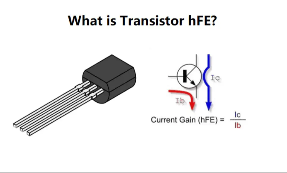
The amplification factor is typically expressed in terms of power. To calculate the current gain, the formula used is:
Gain (hfe) = IC / IB
Where IC is the collector current, and IB is the base current of the circuit.
How to Use A1015?
In the circuit diagram below, an LED flasher circuit using the 2SA1015 transistor is illustrated. Capacitor C1 and resistor R1 are utilized as a frequency generator for the Q1 transistor, which acts as a switch for Q2. Q2, in turn, is responsible for increasing the current. Initially, Q1 conducts as the voltage across C1 rises, allowing current to flow through R2, the LED, and Q2, causing the LED to turn on.
As capacitor C1 discharges through resistor R1 over time, there is a point when C1 is fully discharged. At this stage, there is no voltage biasing the base terminal of Q1, causing Q1 to cease conducting. Consequently, Q2 also stops functioning. As a result, the LED turns off. Subsequently, C1 begins to charge again, restarting the cycle. This continuous process of turning the LED on and off creates the flashing effect.

A1015 Application
Audio Amplification:
The A1015 transistor is widely utilized in audio amplifiers due to its ability to amplify audio signals with minimal distortion and noise. It plays a crucial role in enhancing the strength of audio signals, ensuring clear and high-quality sound output.
Switching:
In electronic circuits, the A1015 transistor serves as a reliable switch, controlling the flow of current. Its efficient switching action enables precise control over various electronic devices, enhancing their overall performance and functionality.
Driver Stage Amplifier Action:
When incorporated as a driver stage in amplifier circuits, the A1015 transistor provides essential current and voltage amplification. This critical function ensures that the amplifier operates efficiently, delivering optimal performance in audio and other signal amplification applications.
AF Amplifier:
Specifically designed for audio frequency (AF) amplification, the A1015 transistor is ideal for use in amplifiers that enhance audio signals for playback through speakers or headphones. Its high-performance capabilities make it a preferred choice for achieving superior sound quality in audio systems.
Darlington Pair:
By configuring the A1015 transistor in a Darlington pair, it is possible to achieve higher current gain and improved performance in amplifier circuits. This configuration enhances the transistor's ability to amplify signals effectively, making it suitable for a wide range of applications requiring high-performance amplification.
LED Flasher:
The A1015 transistor is commonly employed in LED flasher circuits, controlling the flashing of LEDs in various applications such as automotive turn signals or warning lights. Its efficient operation ensures reliable and consistent flashing, enhancing the signaling system's visibility and safety.
Water Level Indicator:
In water level indicator circuits, the A1015 transistor plays a crucial role in detecting the level of water in a tank or reservoir. Its precise and reliable operation ensures accurate monitoring of water levels, enabling efficient management of water resources.
Driver Circuits:
The A1015 transistor is essential in driver circuits, where it drives other components such as relays, motors, or other transistors. Its robust design and reliable performance make it an ideal choice for controlling various electronic devices, ensuring smooth and efficient operation.
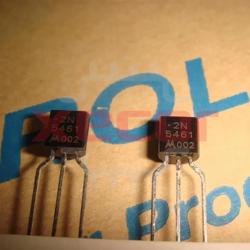
A1015 Package

A1015 Datasheet
Download A1015 Datasheet PDF.
A1015 vs. 2N3906 vs. BC557
| Characteristic | A1015 | 2N3906 | BC557 |
| Polarity | PNP | PNP | PNP |
| Maximum Collector Current (IC) | 150 mA | 200 mA | 100 mA |
| Maximum Collector-Base Voltage (VCBO) | 50 V | 40 V | 50 V |
| Maximum Collector-Emitter Voltage (VCEO) | 50 V | 40 V | 45 V |
| Maximum Emitter-Base Voltage (VEBO) | 5 V | 5 V | 5 V |
| DC Current Gain (hFE) Range | 70 - 400 | 100 - 300 | 125 - 900 |
| Power Dissipation (PD) | 400 mW | 625 mW | 625 mW |
| Transition Frequency (fT) | 80 MHz | 250 MHz | 100 MHz |
| Package Type | TO-92 | TO-92 | TO-92 |
| Common Uses | Audio amplifiers, voltage regulators, low-power applications | Switching and amplification circuits | Audio amplifiers, voltage regulators, low-power applications |
| Advantages | High current gain, low saturation voltage | Low noise, high current capability | High current gain, low noise |
These differences make each transistor suitable for specific applications, ranging from audio amplification and voltage regulation (A1015) to high-speed switching (2N3906) and low-power amplification (BC557). Understanding these distinctions is crucial for selecting the right transistor for a given electronic circuit.
Final Words
In summary, the A1015 PNP transistor is a versatile component with significant importance in various electronic circuits. Its ability to amplify signals, switch loads, and regulate voltages makes it a valuable asset in electronics design. Its reliable performance and versatility make it a popular choice among electronics enthusiasts and professionals alike. As technology continues to advance, the A1015 transistor is expected to remain relevant in future electronic designs, contributing to further innovations in the field.
Read More
FAQ
-
What is the A1015 transistor used for?
The A1015 transistor is commonly used in audio frequency amplifier applications.
-
What is the price of the A1015 transistor?
The A1015 transistor is available on AliExpress at prices ranging from $0.17 to $1.54 per lot, depending on the quantity. For more competitive prices, feel free to request a quote (RFQ) at Xecor.
-
What is the voltage of A1015?
The maximum voltage is 50 V.
-
How does a PNP transistor work?
In a PNP transistor, applying a small negative voltage to the base-emitter junction forward-biases the junction. This enables holes to flow from the emitter, composed of P-type material, to the base, which is made of N-type material.
-
Why would you use a PNP transistor?
PNP transistors can be used to amplify the voltage or current of a signal.
-
Which is better, NPN or PNP transistors?
PNP transistors offer the advantage of a lower turn-on voltage, making them well-suited for high-speed applications. On the other hand, NPN transistors have a higher current-carrying capacity, making them more suitable for low-power applications.

Still, need help? Contact Us: [email protected]