S8050 Datasheet, Equivalent, Working and Uses
Transistors are ubiquitous in electronic projects, serving amplification functions within circuits. The S8050, an NPN Epitaxial Si transistor, is predominantly employed for switching and amplification tasks, making it a staple in various circuit designs. With a remarkable maximum gain capacity of around 400, although typically operating at approximately 110, it proves versatile in amplifier applications.
True to its name, the transistor comprises three layers, with a P-doped layer sandwiched between two N-doped layers. The base terminal corresponds to the P-doped layer, while the emitter and collector terminals are associated with the N-doped layers, respectively. In this article, we'll delve into the S8050 NPN transistor, exploring its datasheet, pinout, circuit diagram, working, uses, equivalents, and more details.

What is S8050?
The S8050 is an NPN transistor designed for low-voltage, high-current applications such as Class B push-pull amplifiers. It operates using electrons as the major carriers and holes as the minor carriers. This transistor has a maximum collector current of 700 mA and a collector-emitter voltage (VCE) of 25 V. To ensure safe operation, the base current should be limited to 5 mA.
As an NPN transistor, the S8050 has three terminals: emitter, base, and collector, which are used for external connections in various circuits. The doping concentration of these terminals differs, with the emitter being heavily doped compared to the collector and base.
The base terminal is lightly doped, while the collector terminal is moderately doped. The transistor uses a small current at one terminal to control a larger current at the other terminals.
The S8050 is classified as a Bipolar Junction Transistor (BJT), a type of transistor that includes both electrons and holes as charge carriers. In the S8050, electrons are the majority of the charge carriers.
The transistor has two PN junctions, EB and CB. The EB junction is forward-biased, while the CB junction is reverse-biased. For optimal performance, the S8050 transistor should operate in a forward-biased condition.
S8050 Pinout
The following figure is S8050 pin diagram:

Pin Configuration
| Pin No. | Pin Name | Description |
| 1 | Emitter | Current Drains out through emitter |
| 2 | Base | Controls the biasing of transistor |
| 3 | Collector | Current flows in through collector |
Functions of Each Pin
- Emitter (E): The emitter is the terminal through which current flows out of the transistor. It is heavily doped to ensure efficient injection of majority carriers (electrons for NPN) into the base.
- Base (B): The base is the control terminal that regulates the flow of current between the emitter and the collector. A small current at the base terminal can control a much larger current flowing between the emitter and collector terminals.
- Collector (C): The collector is the terminal through which current enters the transistor. It is moderately doped to allow for efficient collection of majority carriers (electrons for NPN) from the base.
Features of S8050
- Low Voltage, High Current NPN Transistor: The S8050 is designed to operate at low voltages while handling high currents, making it ideal for use in power supply circuits, motor control, and other applications that require high current switching.
- Small Signal Transistor: Despite its small size, the S8050 can amplify small signals, making it suitable for use in audio amplifiers, signal processing circuits, and other applications where signal amplification is required.
- High Used in push-pull configuration for Class B amplifiers: The S8050 is often used in push-pull configurations for Class B amplifiers, where it helps amplify the input signal while minimizing distortion and power consumption. This feature makes it suitable for use in audio amplifiers and other applications where high-efficiency amplification is required.
- Low Cost: The S8050 is a cost-effective transistor, making it suitable for use in consumer electronics and other applications where cost is a critical factor.
- Low Power Consumption: The S8050 is designed to consume low power, making it suitable for use in battery-operated devices and other applications where power efficiency is important.
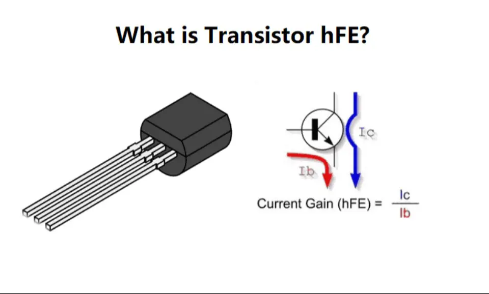
- High Gain: The transistor has a high DC gain (hFE) of typically 120-320, which allows it to effectively amplify weak signals.
- Wide Operating Voltage and Current Range: The S8050 can operate over a wide range of voltages and currents, making it versatile in various circuit designs.
S8050 Specifications
| Type | Parameter |
| Polarity/Channel Type | NPN |
| Maximum DC current gain | 300 |
| Power dissipation | 1 Watt |
| Base-emitter saturation voltage VBE(sat) | 1.2V |
| Collector current | 1.5A |
| Maximum Power | 2 Watt |
| Base- Emitter Voltage ( VBE) | 6V |
| Collector-Emitter Voltage (VCE) | 25V |
| Collector-Base Voltage (VCB) | 40V |
| Current - Collector (Ic) (Max) | 500mA |
| Operating Temperature | -55°C~150°C TJ |
S8050 CAD Model

S8050 Circuit Diagram
The diagram below illustrates the circuit configuration of the S8050 transistor.

In this NPN transistor, electrons serve as the primary charge carriers, unlike in a PNP transistor, where holes are the major charge carriers.
The base is more positively charged relative to the emitter, and the collector voltage must also be more positive than the base voltage.
The collector is physically larger than the base for two reasons: to allow the collector to dissipate more heat without damage and to increase the likelihood of carriers entering the collector terminal.
Two current gain factors are crucial in determining the transistor's characteristics: common-emitter current gain and common-base current gain.
The common-emitter current gain, denoted by β (Beta), is the ratio of collector current to base current. Its value typically ranges from 20 to 1000, with a standard value of 200.
Similarly, the common-base current gain, denoted by α (alpha), is the ratio of collector current to emitter current. Its value generally ranges from 0.95 to 0.99 but is often considered as unity.
S8050 Equivalent/Alternative
S8050 Equivalents
- 2N5830: The 2N5830 is a general-purpose NPN transistor that can be used as an equivalent to the S8050. It has similar characteristics and can be used in similar circuit configurations.
- S9013: The S9013 is another NPN transistor equivalent to the S8050. It can be used in various applications in place of the S8050.
- S9014: The S9014 is a small signal NPN transistor that can be used as an equivalent to the S8050. It has similar specifications and can be used in similar circuit designs.
- 2N5551: The 2N5551 is a high-gain NPN transistor that can be used as an alternative to the S8050. It has similar characteristics and can be used in similar circuit configurations.
S8050 Alternatives
- 2N3904: The 2N3904 is an NPN transistor that can be used as an alternative to the S8050. It is commonly used in amplifiers and switching circuits.
- 2N3906: The 2N3906 is a PNP transistor that can be used as an alternative to the S8050. It is commonly used in amplifiers and switching circuits.
- MPSA42: The MPSA42 is an NPN Darlington transistor that can be used as an alternative to the S8050. It is commonly used in high-gain amplifier circuits.
- SS8050: The SS8050 is a similar transistor to the S8050 and can be used as an alternative. It has similar characteristics and can be used in similar applications.
- BC547: The BC547 is an NPN transistor that can be used as an alternative to the S8050. It is commonly used in general-purpose amplifiers and switching circuits.
- 2N2369: The 2N2369 is an NPN transistor that can be used as an alternative to the S8050. It is commonly used in low-power amplifiers and switching circuits.
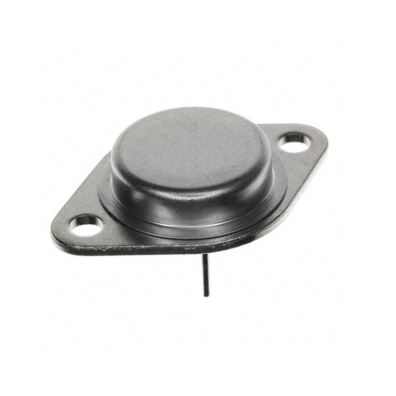
- 2N3055: The 2N3055 is a power NPN transistor that can be used as an alternative to the S8050 in high-power amplifiers and switching circuits.
Complementary PNP Transistors
S8050 in Push-Pull Configuration
The S8050 transistor is often used in a push-pull configuration in Class B amplifiers. Let's discuss how this is achieved.
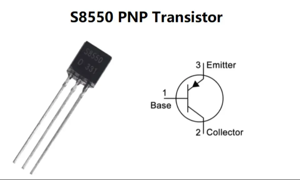
A push-pull amplifier, also known as a Class B amplifier, is a multistage amplifier commonly used for audio amplification in loudspeakers. It is straightforward to construct and requires two identical complementary transistors to operate. "Complementary" means that we need an NPN transistor and its equivalent PNP transistor. In this case, the NPN transistor is the S8050, and its equivalent PNP transistor is the S8550. A simple circuit diagram of a Class B amplifier using the S8050 is shown below.

How Does S8050 Work?
In the S8050 NPN transistor, both the emitter and collector terminals are reverse-biased when the base pin is grounded, and they become closed (forward-biased) when a signal is applied to the base pin. This transistor's maximum gain is 300, which determines its amplification capacity. If the amplification is high, it is used for amplification purposes.
However, the gain value at a collector current is 110, and the maximum current supply through the collector terminal is 700mA, so it cannot control loads that require more than 700mA. The transistor can be biased once the current supply is provided to the base pin, which must be limited to 5mA.
When this transistor is fully biased, it allows up to 700mA of current to flow through the emitter and collector terminals, which is known as the Saturation Region. The typical voltage across the VCE or VCB can be 20V and 30V, respectively. Once the current supply is removed from the base terminal of the transistor, it turns off, entering the cutoff region.
Where and How to Use S8050
The S8050 is commonly used as a general-purpose transistor, making it suitable for a variety of small-scale applications. It is particularly useful in electronic circuits requiring a switch, where it can effectively control loads below the 700mA threshold. This current capacity is adequate for powering many small power household appliances such as LEDs, relays, and bulbs.
Another typical application of the S8050 is in amplification processes, where it can be used to amplify small signals independently.
S8050 Application
The S8050 transistor has a wide range of applications, including:
- Ideal for loudspeaker audio amplification circuits.
- Commonly used in Class B amplifiers and push-pull configurations.
- Well-suited for low-signal applications.
- Suitable for high-gain circuits.
- Useful as a switch, provided the loads are below the 700mA threshold.
- Applicable for amplification from low to high gain.
How to Safely Long Run S8050 in Circuit?
- Ensure the transistor operates below 20V to maintain safe operation within electronic circuits.
- The load in the circuit should operate under 0.7A/700mA to prevent damage.
- Use an appropriate base resistor to limit the current flow at the base terminal to the required level.
- Avoid exposing the transistor to temperatures above 150°C or below -60°C.
S8050 Advantage
The main advantage of the transistor lies in its high gain capacity, which can reach up to 400. This high gain is valuable for amplification purposes. Additionally, the transistor can also operate at low gain, particularly under normal operating current. This versatility allows engineers to design electronics with different levels of amplification.
S8050 Package

S8050 Datasheet
Download S8050 Datasheet PDF.
S8050 vs. 2N2222
| Feature | S8050 | 2N2222 |
| Maximum Collector Current (IC) | Around 100mA | Around 800mA |
| Package Types | TO-92, SOT-23 (possibly) | TO-92, TO-18, TO-39, SOT-23 (possibly) |
| High Frequency Performance | Slightly different due to internal structure and materials | May vary, generally good for high frequency applications |
| Current Amplification (hFE) | Value may vary | Value may vary |
| Operating Temperature Range | -65°C to 150°C | -65°C to 200°C |
| Temperature Coefficient | May vary | May vary |
| Thermal Stability | May vary | May vary |
| Applications | Signal generator, sensor interface, low power amplifier, signal conditioning | Sensor interface, switching circuit, signal amplifier, signal conditioning, current amplification |
S8050 vs. SS8050
| Feature | S8050 | SS8050 |
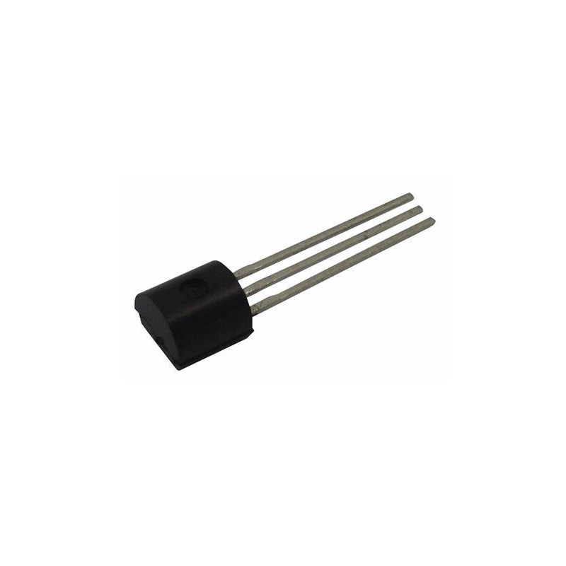
| Package Type | TO-92 (Through-Hole) | SOT-23 (Surface-Mount) |
| Package Size | Larger | Smaller |
| Mounting Method | Through-Hole | Surface-Mount |
| Lead Count | 3 (Collector, Base, Emitter) | 3 (Collector, Base, Emitter) |
| Electrical Characteristics | Generally Similar | Generally Similar |
| Applications | Through-Hole PCB designs | Surface-Mount applications |
S8050 vs. BC547
| Feature | S8050 | BC547 |
| 1st Pin (Emitter/Collector) | Emitter | Collector |
| 2nd Pin (Base) | Base | Base |
| 3rd Pin (Collector/Emitter) | Collector | Emitter |
| Collector-Emitter Voltage (Vceo) | 25V | 45V |
| Collector Current (Ic) | 500mA | 100mA |
| Total Device Dissipation (PD) | 1000mW | 625mW |
| DC Current Gain (hFE) | 85 To 300 | 110 To 800 |
| Frequency (fT) | 100 MHz | 300 MHz |
Conclusion
The S8050 is a general-purpose transistor with a small signal, less voltage, and high current used to perform different tasks in electronic circuits. It plays a crucial role in modern electronic circuits, offering a balance between performance and cost-effectiveness. Its versatility and reliability make it a popular choice among hobbyists and professionals alike for various projects.
Read More
FAQ
-
What is the S8050 transistor used for?
The S8050 is primarily used in Class B Push-Pull amplifier circuits.
-
Is S8050 an NPN or PNP transistor?
The S8050 is an NPN transistor.
-
What is the maximum current of the S8050 transistor?
700mA.
-
What can an S8050 transistor be used to switch on loads under 700mA?
It can be used as a switch in electronic circuits.
-
Can I use BC547 instead of S8050?
Yes.
-
What is the difference between s8050 and s8550?
The circuit with the S8050 (NPN transistor) illuminates when the button is pressed, indicating a high-level conduction circuit. Conversely, the circuit with the S8550 (PNP transistor) illuminates when the button is released, indicating a low-level conduction circuit. Refer to this article for more information about s8050 vs. s8550.
-
What is the function of the sot 23 transistor?
SOT23 packages are commonly used for flexible switching and amplification of electrical signals and power in consumer electronics.

 Dr. James Anderson

Still, need help? Contact Us: [email protected]