ESP-01 Pinout, Programming, Datasheet, and ESP-01 vs. ESP-01S vs. ESP8266
 Prof. David Reynolds
Published:February 28, 2024
The ESP-01 WiFi module is a popular choice for adding wireless connectivity to various projects. Its small size and low cost make it ideal for Internet of Things (IoT) applications, home automation, and more. In this ultimate guide, we'll explore ESP-01 pinout, specification, programming, comparison with ESP-01S and ESP8266, etc. Everything you need to know about the ESP-01 WiFi module.
What is ESP-01?
The ESP-01 is a WiFi module that enables easy access to WiFi networks for microcontrollers. It is widely used in the industry and combines various components such as antenna switches, a Radiofrequency balun, a power amplifier, a low-noise receiver amplifier, and power management elements.
This module requires minimal internal circuitry, and its entire solution, including the front-end module, is designed to occupy a small PCB area. The ESP-01 module is considered a system-on-chip (SOC) because it can function as a standalone microcontroller, eliminating the need to interface with another microcontroller (e.g., Arduino, Atmel, PIC microcontroller, etc.) to use its I/O pins.
The ESP-01 also integrates an advanced version of Tensilica's L-106 diamond series 32 SRAM with WiFi functionalities. It can be interfaced with specific devices through its GPIOs, and code for such applications is provided in the SDK.
ESP-01 Pinout
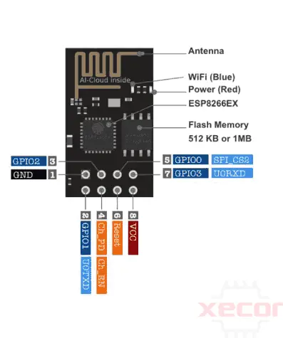
Description of ESP-01 Pinout
| Pin Nmae | Pin Function | Description |
| VCC | Power supply (3.3V) | The VCC pin on the ESP-01 module provides a 3.3-volt power supply. It requires a positive supply. |
| GND | Ground | The GND pin, also known as the ground pin, connects the board to ground. It requires a negative supply. |
| TX | Transmit Data (Connected to the LED) | The TX pin, or GPIO 1, can be a serial output or a normal input/output pin. It is used for transmitting data. |
| RX | Receive Data | The RX pin, or GPIO 3, is a serial input or normal input/output pin. Its primary function is to receive data. |
| CH_PD | Chip Power Down (Active High) | The CH_PD pin, also known as the Chip Power Down or Chip Enable pin, enables the chip. It is an active high pin, so pulling it high enables the chip. |
| RST | Reset (Active Low) | The RESET pin resets the board. It is an active low pin, meaning the board is reset when this pin is pulled low. |
| GPIO0 | General-purpose I/O 0 | A general-purpose input/output pin. |
| GPIO2 | General-purpose I/O 2 | Another general-purpose input/output pin. |
ESP-01 WiFi Module Specifications
Power Supply:
- Voltage: 3.0V ~ 3.6V
- Current: >300mA
Current Consumption:
- Continuous Transmission: Average: ~71mA, Peak: 300mA
- Modem Sleep: ~20mA
- Light Sleep: ~2mA
- Deep Sleep: ~0.02mA
SPI Flash Memory:
Default: 8Mbit (1MB)
Interface:
- UART/GPIO
- IO Port: 2
UART Baud Rate:
- Support: 300 ~ 4608000 bps
- Default: 115200 bps
Frequency Range:
2412 ~ 2484MHz
Transmit Power:
- 802.11b: 16±2 dBm (@11Mbps)
- 802.11g: 14±2 dBm (@54Mbps)
- 802.11n: 13±2 dBm (@HT20, MCS7)
Receiving Sensitivity:
- CCK, 1 Mbps: -90dBm
- CCK, 11 Mbps: -85dBm
- 6 Mbps (1/2 BPSK): -88dBm
- 54 Mbps (3/4 64-QAM): -70dBm
- HT20, MCS7 (65 Mbps, 72.2 Mbps): -67dBm
Features of ESP-01
- 802.11 b/g/n
- Integrated low-power 32-bit MCU
- Integrated 10-bit ADC
- Integrated TCP/IP protocol stack
- Integrated TR switch, balun, LNA, power amplifier, and matching network
- Integrated PLL, regulators, and power management units
- Supports antenna diversity
- WiFi 2.4 GHz, supports WPA/WPA2
- Supports STA/AP/STA+AP operation modes
- Supports Smart Link Function for both Android and iOS devices
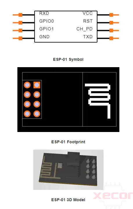
ESP-01 CAD Model
Absolute Maximum Ratings
| Rating | Value |
| Storage Temperature | -40 to 125℃ |
| Maximum Soldering Temperature | 260℃ |
| Supply Voltage | +3.0 to +3.6V |
Power Consumption OF ESP-01
| Parameters | Typical |
| Tx802.11b, CCK 11Mbps, P OUT=+17dBm | 170mA |
| Tx 802.119,OFDM 54Mbps, P OUT =+15dBm | 140mA |
| Tx 802.11n,MCS7,P OUT-+13dBm | 120mA |
| Rx 802.11b,1024 bytes packet length,-80dBm | 50mA |
| Rx 802.11g,1024 bytes packet length,-70dBm | 56mA |
| Rx 802.11n, 1024 bytes packet length,-65dBm | 56mA |
| Modem-Sleep | 15mA |
| Light-Sleep | 0.9mA |
| Deep-Sleep | 10uA |
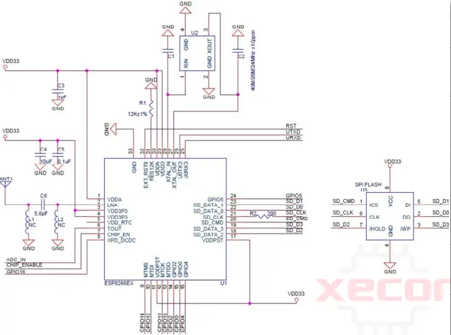
ESP-01 Schematic
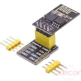
ESP-01 Module Breadboarding and Adapters
You cannot directly insert the ESP-01 module when setting up a breadboard. In the past, various tricks were used to adapt the ESP-01 module for breadboarding, such as bending the header pins or creating a DIY adapter. Fortunately, inexpensive breadboard adapters for the ESP-01 module are now available, as shown in below figure.
If you plan to connect the ESP-01 board to an Arduino board, keep the following two (2) points in mind:
- Do not power the ESP-01 module with the 3.3V output from the Arduino board, as the ESP-01 module may require up to 300mA of current, which could cause the 3.3V regulator on the Arduino board to overheat and become damaged.
- Use logic level translation between the ESP-01 and the Arduino board, as the Arduino board uses 5V logic while the ESP-01 module uses 3.3V logic.
A suitable ESP-01 adapter for interfacing with Arduino boards is depicted in below figure. It includes a built-in 3.3V regulator and two (2) bi-directional logic level converters for the RX and TX pins.
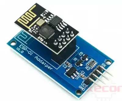
ESP-01 Adapter with Voltage Regulator and Logic Translator
The schematic diagram for the adapter is shown in the following figure.
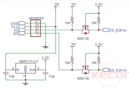
Schematic Diagram of ESP-01 Adapter
Programming of ESP-01
To program the ESP-01 using the Arduino IDE, you must first install the ESP board into your Arduino IDE software. Unlike the ESP-8266 or other upper variants, the ESP-01 board does not have an onboard FTDI programmer. Therefore, you can use an Arduino board to program it or a USB FTDI programmer.
Programing ESP-01 Using Arduino Board
Connection
Here are the instructions for connecting the ESP-01 to an Arduino board:
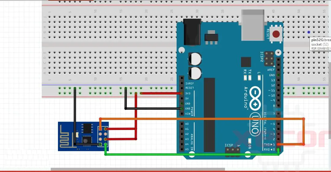
Connection for Programming:
- Connect the Ground pin of the ESP-01 to the Ground pin of the Arduino.
- Connect GPIO 0 of the ESP-01 to the Ground pin of the Arduino.
- Connect the RXD pin of the ESP-01 to the RX pin of the Arduino.
- Connect the TXD pin of the ESP-01 to the TX pin of the Arduino.
- Connect the CHPD pin of the ESP-01 to the 3.3V pin of the Arduino.
- Connect the VCC pin of the ESP-01 to the 3.3V pin of the Arduino.
- GPIO-2 and RST pins of the ESP-01 will not be connected.
- Before uploading the code, set GPIO 0 to ground and connect RST to ground. Remove RST after half a second, and then click on upload. The blue LED should flash once and then blink till the code is uploaded.
Connection After Programming:
- After programming, remove the serial Arduino cable and then plug it in again.
- Disconnect GPIO-0 from GND.
- Connect the GND pin of the ESP-01 to the GND pin of the Arduino.
- GPIO 0, GPIO 2, and RST pins remain not connected.
- Connect the RXD pin of the ESP-01 to the TX pin of the Arduino.
- Connect the TXD pin of the ESP-01 to the RX pin of the Arduino.
- Connect the CHPD pin of the ESP-01 to the 3.3V pin of the Arduino.
- Connect the VCC pin of the ESP-01 to the 3.3V pin of the Arduino.
Code
Here are the steps to add the ESP8266 board to the Arduino IDE:
- Open the Arduino IDE.
- Go to Files -> Preferences.
- In the Additional Boards Manager URLs section, paste the following URLs:https://dl.espressif.com/dl/package_esp32_index.json, http://arduino.esp8266.com/stable/package_esp8266com_index.json.
- Click OK.
- Go to Tools -> Board -> Boards Manager.
- Search for ESP8266 and click Install.
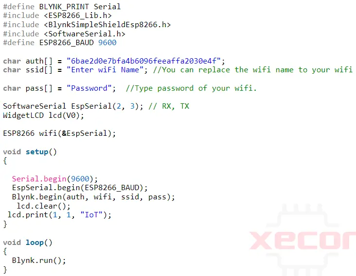
- After installation, select the Generic ESP8266 module from there. The code is as follows:
Programing ESP-01 Using FTDI programmer
Connection
Here are the instructions for connecting the ESP-01 module to an FTDI programmer:
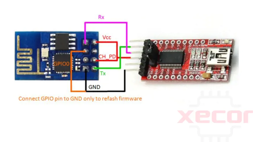
- Connect the VCC of the FTDI programmer to the VCC of the ESP-01 module.
- Connect the CH_PD of the FTDI programmer to the GPIO 0 of the ESP-01 module.
- Connect the GND of the FTDI programmer to the GND of the ESP-01 module.
- Connect the TX of the FTDI programmer to the RX of the ESP-01 module.
- Connect the RX of the FTDI programmer to the TX of the ESP-01 module.
- Ground the GPIO 0 of the ESP-01 module to enter programming mode.
- Connect the FTDI cable to a USB port on your computer.
These steps complete the connection between the FTDI programmer and the ESP-01 module.
Code
Here are the steps to follow before uploading the code in Arduino IDE:
- Open the Arduino IDE.
- Navigate to File > Preferences.
- In the Additional Board Manager URLs field, paste the following link: http://arduino.esp8266.com/stable/package_esp8266com_index.json.
- Go to Tools > Boards > Boards Manager.
- Search for ESP8266 and click the Install button to install the ESP8266 Board.
- Select the Generic ESP8266 Module from the board selection list.
- Now, you can upload the code provided below.
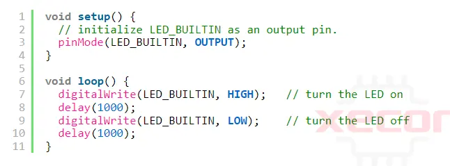
After uploading the Blink LED program, connect the LED to the GPIO_2 Pin of the ESP8266.
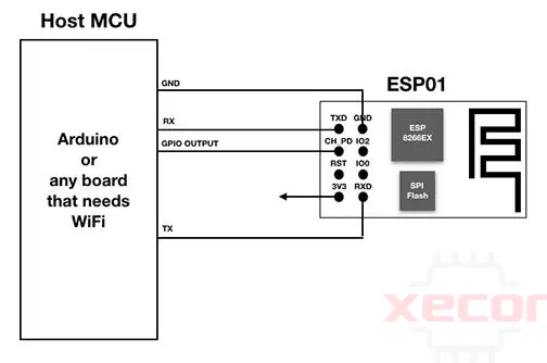
How to use ESP-01 as a WiFi Shield?
We developed an improved method for utilizing the ESP-01 as a WiFi shield. The ESP-01 manages WiFi and HTTP(S) connections in this setup, as described in "Using the ESP-01 with Arduino." The ESP-01 communicates with a sensor node, such as an STM32 Blue Pill, over a serial interface. This approach resembles using the ESP-01 with AT command firmware, but instead, the ESP-01's firmware is replaced with the Arduino web client. This modification lets us define our communication requests and responses between the serial interfaces.
ESP-01 vs. ESP-01S: A Comparison
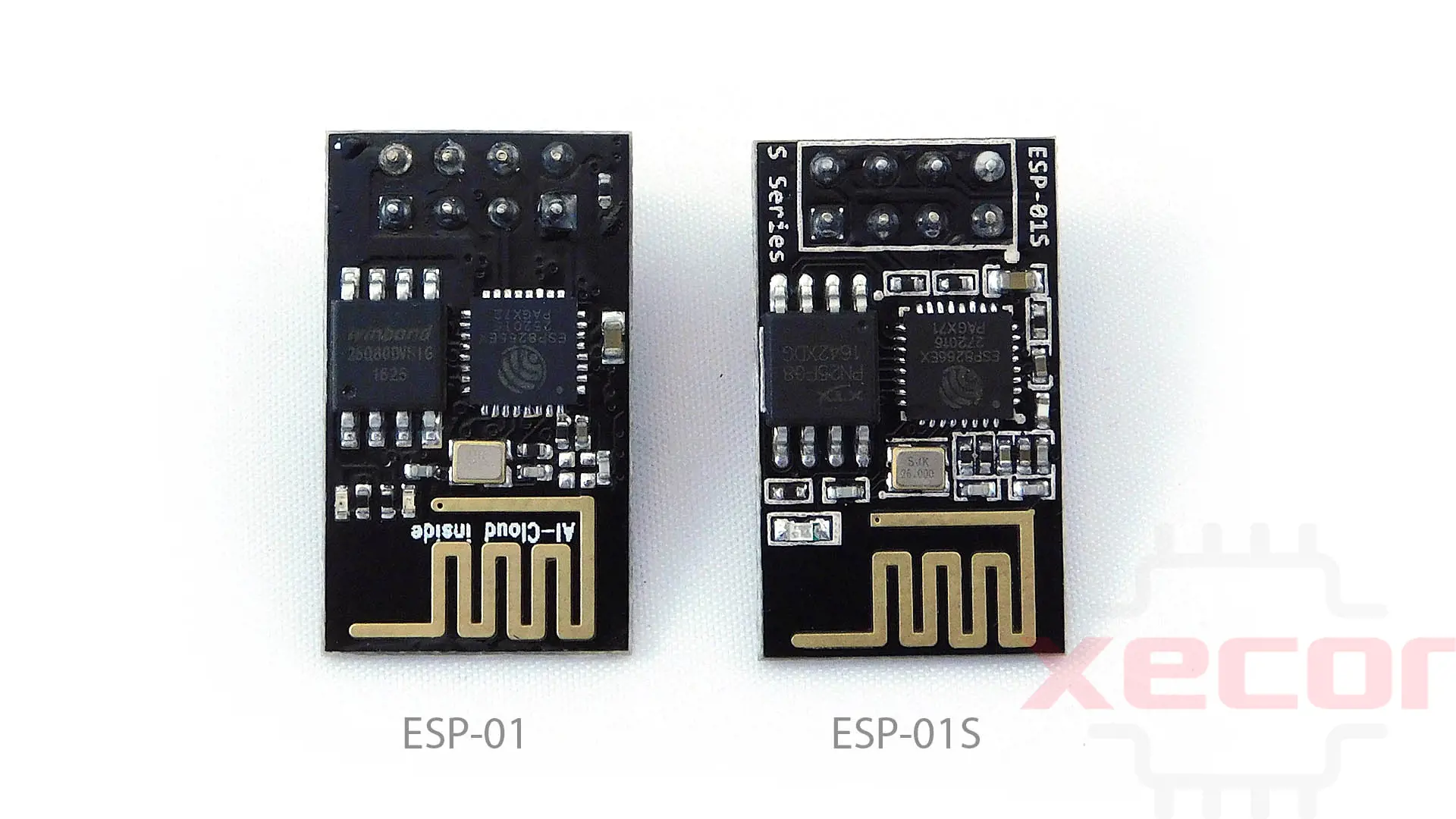
The ESP-01 is an older model, while the ESP-01S is newer. The primary difference lies in the on-board memory size, with the ESP-01S having larger memory.
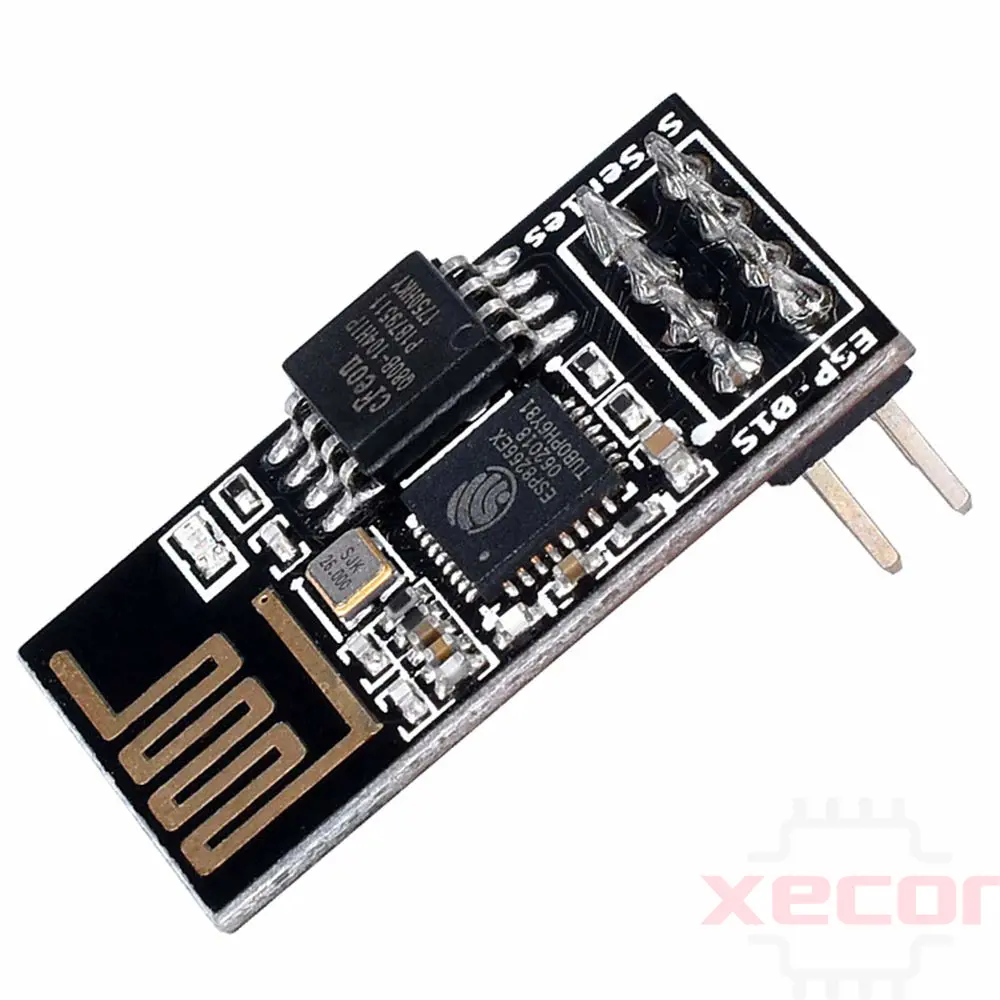
Functionally, both boards can be programmed using the ESP-01 programmer, with the ESP-01S operating similarly to the ESP-01. One noticeable difference is the absence of TX or Power LEDs on the ESP-01S; instead, it features a single LED connected to GPI02.
The ESP-01 includes two LEDs near the PCB antenna, one for the Tx line (GPIO1) and the other as a power indicator. In contrast, the ESP-01S has a single blue LED wired to GPIO2. Additionally, the ESP-01S has two extra pull-up resistors visible between the ESP8266EX chip and the header pins. One of these resistors is located between the CH PD and 3V3 (VCC) pins.
The ESP-01S typically comes with a 4MB serial flash, four times larger than the ESP-01. This larger memory makes the ESP-01S more reliable, as the pull-ups ensure no random signals interfere with RST or CH_PD.
The single pull-up on the GPIO0 pin allows for easy push-button operation. Furthermore, the single LED (active low) on GPIO2 enables programmable control of an LED, which can also function as a status indicator (e.g., indicating when a relay is on or off).
ESP-01 vs ESP-01S: what's the difference?
| Feature | ESP-01 | ESP-01S |
| Flash size | 1 MByte | 4 MByte |
| Flash Memory | 512 Mo | 1 Mo |
| Color | Blue | Black |
| Pull-ups | none | 3 |
| LEDs | 2 | 1 |
| Programmable LEDs | none | 1 |
| Reliability | Floating RST and CH_PD | Better |
| Programming interface | Serial RX, TX etc. | Identical |
| Possible mention | AI Cloud Inside | S Series |
| Note | / | The red (Power) and blue (WiFi) LEDs are placed next to the antenna engraved on the PCB |
In summary, while the ESP-01 and ESP-01S are quite similar, their main distinctions lie in the flash memory chip and the LED configuration on GPIO2.
ESP-01 vs. ESP8266: Which One to Choose?
The ESP-01 is essentially an ESP8266 module mounted on a compact development board (24.8 x 14.3mm). The board exposes only two pins of the ESP8266EX module, GPIO0, and GPIO2, as well as the RX and TX pins for programming and debugging via the serial port.
The only difference between versions is the amount of flash memory, 512KB or 1MB.
ESP-01 Datasheet
Download the ESP-01 Datasheet PDF.
Conclusion
The ESP-01 WiFi Module is a versatile and cost-effective solution for IoT projects, offering reliable performance and connectivity. Its compact size and compatibility with popular development platforms like Arduino make it accessible to many users. By understanding its pinout, programming options, and datasheet, developers can unlock the full potential of the ESP-01 in their projects.
Read More
FAQ
-
What is ESP-01 used for?
The ESP-01 is a WiFi module that enables easy access for microcontrollers to connect to WiFi networks.
-
How does ESP-01 Work?
The ESP-01 can be managed through your local WiFi network or the internet (with port forwarding). It features GPIO pins that can be programmed to control an LED's ON/OFF state or relay over the internet. Programming the module via an Arduino/USB-to-TTL converter using the serial pins (RX, TX).
-
How do I connect my ESP-01 to WiFi?
To check if it's working, access your computer's WiFi settings, locate a network named "ESP8266 Access Point," use the password "there is no spoon," and connect to it. Then, open a terminal and ping 192.168.4.1 (this is the default IP address of our ESP AP). You should see the ESP responding to your pings.
-
Is ESP-01 programmable?
The ESP-01 module features GPIO pins that can be programmed to remotely control the operation of an LED or a relay over the internet.
-
How do I put ESP-01 in programming mode?
Before uploading the code, press and hold the RST button, then press the GPIO0 button while holding the RST button. Next, release the RST button, followed by releasing the GPIO0 button. The ESP-01 will now enter programming mode.
-
How can I control ESP-01 without a router?
To control the ESP-01 ESP8266 module without a router or an internet connection, the ESP-01 is placed into AP mode (Access Point mode). A smartphone or a PC with wireless capability is then used to connect to the module. Command codes are then sent to it through a browser or an application.
-
What is the difference between ESP-01 and S?
The main difference between the ESP-01 and the ESP-01S is the increased memory capacity of the ESP-01S.
-
What is the difference between ESP8266 and ESP01?
The ESP-01 WiFi Module and ESP8266 are both built around the ESP8266 SoC. The key difference is that the ESP-01 offers only 2 GPIOs, whereas the ESP8266 provides 7 GPIOs.

Still, need help? Contact Us: [email protected]