A Comprehensive to NodeMCU ESP8266 Pinout
 Prof. David Reynolds
Published:January 31, 2024
NodeMCU can receive power through a Micro USB jack or the VIN pin (External Supply Pin) and offers support for UART, SPI, and I2C interfaces.
Developed as an open-source firmware, hardware, and software project, NodeMCU initially targeted the ESP8266 Wi-Fi SoC chip using LUA. Its remarkable attributes include being a cost-effective, compact, and potent board, tailor-made for IoT applications. Compatibility with Arduino IDE and MicroPython expedites the prototyping process, contributing to its status as the most popular and sought-after board in the electronics market. In this article, we will delve into the NodeMCU ESP8266 pinout, explore its function, and learn how to use it in your project.

Overview of NodeMCU ESP8266
The NodeMCU ESP8266 development board is equipped with the ESP-12E module housing the ESP8266 chip, featuring the Tensilica Xtensa 32-bit LX106 RISC microprocessor. Operating at an adjustable clock frequency ranging from 80MHz to 160MHz, this microprocessor supports RTOS. NodeMCU boasts 128 KB of RAM and 4MB of Flash memory for data and program storage. Its robust processing capabilities, coupled with built-in Wi-Fi/Bluetooth and Deep Sleep Operating features, render it well-suited for IoT projects.
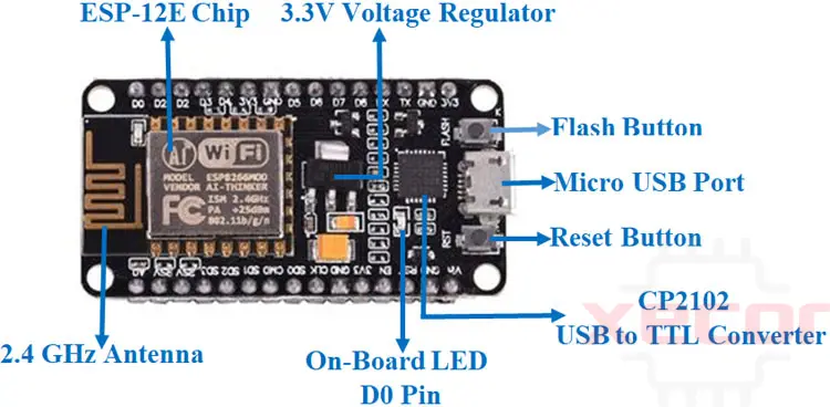
NodeMCU ESP8266 Pinout
The NodeMCU ESP8266 features 17 GPIO pins, with 11 of them available for general use. Out of these, 6 are dedicated to communication with the onboard flash memory chip. Additionally, some GPIO pins support PWM functionality, allowing them to interface with sensors and actuators in the external environment. The board is also equipped with UART, SDIO, SPI, I2C, I2S, and an IR remote control peripheral.

NodeMCU Development Board Pin Configuration

Power Pins
Micro-USB:
The Micro-USB port stands as a vital gateway for powering the NodeMCU Development Board. Through this port, the board can draw power from an external source, typically a computer or a USB power adapter. This feature enhances the board's versatility, making it conveniently accessible for a wide array of applications.
3.3V:
This pin is designated for the regulated 3.3 volts power supply to the NodeMCU. The regulated nature of the power ensures a stable and consistent energy flow to the board. Users can connect an appropriate power source to this pin, reinforcing the reliability of the board's performance in diverse electronic projects.
GND:
Ground pins are fundamental components in any electronic setup, providing a reference potential for the circuit. The Ground pin on the NodeMCU Development Board serves this essential function, completing the electrical circuit and stabilizing the voltage levels. A stable ground connection is imperative for the proper functioning and integrity of the board.
Vin:
The Vin pin, short for Voltage In, serves as a port for an external power supply. This allows users to provide power to the NodeMCU Development Board from an independent source, offering flexibility in choosing the most suitable power input based on the specific requirements of the project. It is particularly useful in scenarios where the Micro-USB port might not be the preferred or available power source.
Control Pins
EN (Enable) Pin:
The Enable pin, denoted as EN, is a crucial element in the NodeMCU's control infrastructure. This pin acts as a switch, allowing or restricting the flow of power to the microcontroller. By manipulating the state of the EN pin, users gain the ability to turn the entire microcontroller unit on or off. This functionality proves invaluable in scenarios where power conservation or controlled activation/deactivation of the board is imperative for optimal energy management.
RST (Reset) Pin:
The Reset pin, abbreviated as RST, plays a fundamental role in restoring the microcontroller to its default state. When triggered, either through external intervention or by utilizing an integrated button, the RST pin initiates a reset mechanism. This action effectively clears the current state of the microcontroller, reverting it to its initial configuration. Such a reset feature is indispensable for troubleshooting, debugging, or preparing the NodeMCU for a fresh start in various applications.
The synergy between the EN and RST pins provides users with a dynamic control mechanism, empowering them to manage the NodeMCU's operational state with precision. Whether it's selectively activating or resetting the microcontroller, these control pins contribute to the versatility and adaptability of the NodeMCU Development Board in diverse electronic endeavours.
Analog Pin
A0 (Analog Pin 0):
A0, representing Analog Pin 0, is designated for the meticulous task of gauging analog voltage levels within the board's operational spectrum. This pin operates within the voltage range of 0 to 3.3V, offering a window into the subtle nuances of analog signals. Its role is particularly crucial in scenarios where the analysis of continuous and varied voltage values is essential for the accurate interpretation of sensory input or environmental data.
By interfacing with sensors, transducers, or other analog devices, A0 transforms real-world analog phenomena into quantifiable electrical signals. This conversion is instrumental in applications such as environmental monitoring, sensor-based systems, or any scenario where nuanced voltage readings contribute to a comprehensive understanding of the physical world.
The strategic placement of A0 within the Analog Pin category underscores its importance in facilitating nuanced and context-rich measurements, thereby enhancing the NodeMCU Development Board's capabilities in applications demanding precision and sensitivity to analog input variations.
GPIO Pins

GPIO1 to GPIO16:
The GPIO Pins, ranging from GPIO1 to GPIO16, collectively represent a dynamic ensemble of 16 General Purpose Input-Output pins embedded within the NodeMCU architecture. These pins are instrumental in facilitating bidirectional communication, enabling users to configure them either as inputs to receive external signals or as outputs to convey data to external components.
Each GPIO pin within this spectrum is programmable, offering users the flexibility to tailor their functionality based on the unique requirements of a given project. Whether it's interfacing with sensors, driving actuators, or establishing communication with other microcontrollers, these GPIO pins serve as the digital conduits for a diverse array of applications.
The NodeMCU's provision of 16 GPIO pins underscores its adaptability to a wide range of electronic projects. This rich assortment of configurable pins empowers developers and enthusiasts to craft intricate and customized solutions, harnessing the full potential of the NodeMCU Development Board in the realm of embedded systems, IoT (Internet of Things), and various electronic applications.
SPI Pins
SD1 (Slave Data Input/Output 1):
SD1, or Slave Data 1, is a pivotal SPI pin that plays a crucial role in bidirectional data transfer. This pin serves as a conduit for transmitting data from the NodeMCU to a connected peripheral or receiving data from an external device. Its bidirectional nature enhances the versatility of the SPI communication, allowing for a seamless flow of information between the NodeMCU and peripheral devices.
CMD (Command):
The CMD pin assumes the role of signalling and control in the SPI communication process. It is responsible for conveying command signals from the NodeMCU to external devices, dictating the nature of the data transfer. This pin acts as a crucial coordinator, orchestrating the SPI transactions and ensuring synchronized communication between the NodeMCU and connected peripherals.
SD0 (Slave Data Input/Output 0):
SD0, akin to SD1, operates as a bidirectional channel for data exchange. It facilitates the reception of data from external peripherals or transmits data from the NodeMCU to the connected devices. This bidirectional characteristic enhances the efficiency of data transfer, enabling the NodeMCU to interact seamlessly with a diverse array of SPI-compatible peripherals.
CLK (Clock):
The CLK pin, often referred to as the Clock pin, serves as the heartbeat of SPI communication. It generates a clock signal that synchronizes the timing of data transmission between the NodeMCU and connected peripherals. This synchronized clock pulse ensures a harmonious and organized flow of data, contributing to the reliability and accuracy of SPI communication.
UART Pins
TXD0 (Transmit Data 0):
TXD0 stands as the Transmit Data pin for UART0, the primary UART interface on the NodeMCU. This pin is responsible for transmitting serial data from the NodeMCU to external devices or peripherals. It acts as the outbound channel for data leaving the board, playing a key role in the communication between the NodeMCU and connected devices.
RXD0 (Receive Data 0):
The RXD0 pin, denoting Receive Data for UART0, operates as the entry point for incoming serial data. It captures and relays data received from external devices to the NodeMCU. This bidirectional nature of RXD0 ensures a seamless exchange of information, establishing a channel for data reception and facilitating communication between the NodeMCU and connected peripherals.
TXD2 (Transmit Data 2):
TXD2, part of UART1, serves as the Transmit Data pin for the secondary UART interface. This pin is instrumental in transmitting data during communication sessions involving UART1. While UART0 is primarily used for general communication, TXD2 extends the NodeMCU's capabilities by providing an additional channel for transmitting data in more specialized scenarios.
RXD2 (Receive Data 2):
RXD2, corresponding to Receive Data for UART1, functions as the entry point for serial data received during UART1 communication. This pin complements TXD2, enabling the NodeMCU to receive data from external sources using the secondary UART interface. It adds versatility to the board's communication capabilities, supporting specific applications that may necessitate a dedicated UART channel.
UART1 and Firmware Upload:
It's noteworthy that UART1, specifically involving RXD2 and TXD2, assumes a crucial role in the firmware upload process. During firmware upload, data is transmitted from an external source to the NodeMCU through UART1. This is a pivotal function as it allows users to seamlessly update and modify the board's firmware, ensuring its adaptability to evolving project requirements.
I2C Pins
The NodeMCU accommodates I2C functionality through specific pins, yet a distinctive aspect of their internal versatility necessitates a closer examination to pinpoint the dedicated I2C connections. I2C, a widely adopted serial communication protocol, facilitates the seamless exchange of data between the NodeMCU and various peripherals, such as sensors, displays, or other microcontrollers.
In navigating the I2C Pins on the NodeMCU, users encounter a scenario where the exact pins tailored for I2C are embedded within the broader array of the board's interface. The internal functionality of these pins extends beyond I2C, thus requiring users to engage in a thoughtful exploration to identify and leverage the specific pins dedicated to I2C communication.
ESP8266 On-board LED
The on-board LED is linked to GPIO2.
Reset Pin
You can reset the board in two ways: either by pressing the reset button or by pulling the reset pin LOW.
NodeMCU ESP8266 Specifications
| Specification | Value |
| Microcontroller | ESP8266 |
| Processor | Tensilica L106 32-bit RISC microcontroller |
| Clock Speed | 80MHz (default), adjustable up to 160MHz |
| Flash Memory | 4MB |
| RAM | 80KB (instruction RAM), 50KB (data RAM) |
| Wi-Fi | 802.11 b/g/n |
| GPIO Pins | 17 (including GPIO 16 used for wake-up) |
| Digital I/O Pins | 17 |
| Analog Input Pins | 1 (A0) |
| UART Interfaces | 1 (TX/RX) |
| SPI Interfaces | 1 |
| I2C Interfaces | 1 |
| ADC Channels | 1 (10-bit) |
| Operating Voltage | 3.3V |
| Input Voltage | 7-12V |
| Operating Current | ~70mA (average) |
| USB Interface | Micro USB |
Other Espressif Boards
ESP8266, ESP12E, ESP32(Refer to this article for more information about the difference between ESP32 and ESP8266.)
Other Development Boards
Arduino, Raspberry Pi(We provide Raspberry Pi RP2040 for your exploring), PIC Development Board, AVR Development Board, MSP430 Launchpad, Intel Edison, Beagle Bone
Programming NodeMCU ESP8266 with Arduino IDE
Programming the NodeMCU Development Board using the Arduino IDE is a straightforward process due to its user-friendly nature.
Programming the NodeMCU with the Arduino IDE typically takes only 5-10 minutes. All that's required is the Arduino IDE, a USB cable, and the NodeMCU board. For detailed instructions, you can refer to the Getting Started Tutorial for NodeMCU to set up your Arduino IDE for NodeMCU programming.
How to Upload Your First Program
After installing the Arduino IDE on your computer:
- Connect the board to the computer using the USB cable.
- Open the Arduino IDE, and select the correct board by navigating to Tools > Boards > NodeMCU 1.0 (ESP-12E Module).
- Choose the appropriate port by selecting Tools > Port.
To initiate the NodeMCU board and execute the blink function on the built-in LED, load the example code by going to Files > Examples > Basics > Blink. Once the example code is loaded, click the 'upload' button on the top bar. After the upload is complete, you should observe the built-in LED of the board blinking.
NodeMCU ESP8266 Applications

NodeMCU ESP8266, with its integrated Wi-Fi and Bluetooth capabilities, finds diverse applications across various projects. Some notable applications include:
Prototyping of IoT Devices:
NodeMCU is widely employed for prototyping Internet of Things (IoT) devices. Its connectivity features make it suitable for projects involving sensor data, remote monitoring, and IoT applications.
Low Power Battery Operated Applications:
Due to its low power consumption and the ability to operate on battery power, NodeMCU is ideal for applications where energy efficiency is crucial. This makes it suitable for remote sensor nodes and battery-operated IoT devices.
Network Projects:
NodeMCU serves as a robust platform for network-related projects. Its Wi-Fi capabilities enable seamless integration into local networks, making it suitable for applications like network monitoring, data logging, and communication projects.
Projects Requiring Multiple I/O Interfaces with Wi-Fi and Bluetooth Functionalities:
The NodeMCU's versatility shines in projects that demand multiple input/output interfaces coupled with wireless connectivity. It can be used in applications where both Wi-Fi and Bluetooth functionalities are essential, providing a flexible solution for diverse project requirements.
Home Automation Systems:
NodeMCU is often utilized in home automation projects, enabling users to control and monitor various devices remotely through Wi-Fi. This includes applications such as smart lighting, temperature control, and security systems.
Educational Projects:
NodeMCU is popular in educational settings for teaching and learning about IoT, wireless communication, and embedded systems. Its ease of use and compatibility with the Arduino IDE make it accessible to students and hobbyists.
Weather Stations:
Building weather monitoring stations is another application of NodeMCU. Its connectivity features allow it to gather weather data from sensors and transmit it to online platforms for analysis and display.
Smart Agriculture:
In agriculture, NodeMCU can be employed for smart farming applications. This includes monitoring soil moisture levels, weather conditions, and automated irrigation systems.
NodeMCU ESP8266 Datasheet
Download NodeMCU ESP8266 Datasheet PDF.
Conclusion
The NodeMCU ESP8266, a potent and adaptable platform, opens the doors to a realm of boundless possibilities for IoT applications and DIY projects. With its affordability and user-friendly nature, it has garnered significant popularity among both hobbyists and professionals, backed by a vast community. Understanding the NodeMCU ESP8266 pinout facilitates effective hardware design and integration into IoT projects. This detailed guide provides you with a thorough understanding of its internal mechanisms and capabilities. Whether you're a beginner or an expert, the NodeMCU ESP8266 stands as an essential tool for your upcoming project.
Read More
FAQ
-
What is the pinout of NodeMCU ESP8266?
The ESP8266 NodeMCU features a total of 17 GPIO pins.
-
Is NodeMCU the same as ESP8266?
NodeMCU, a development board, is built around the ESP8266 chip as its core but comes with additional features like built-in Wi-Fi and a USB-to-serial converter. While not precisely identical, NodeMCU is based on the ESP8266.
-
Why choose NodeMCU ESP8266?
The NodeMCU ESP8266 is widely utilized as a development board in IoT applications, offering a versatile and cost-effective solution for connecting devices to the internet. It incorporates Wi-Fi and programming capabilities, enabling rapid prototyping and deployment of IoT solutions. The board's compatibility with the Arduino IDE and a wide range of libraries simplifies programming. Its compact size and low power consumption make it suitable for various applications, from home automation to industrial control systems.
Still, need help? Contact Us: [email protected]