In-Depth Explanation of UART Communication
UART (Universal Asynchronous Receiver/Transmitter) is a widely used serial communication protocol commonly employed in communication between microcontrollers and various embedded devices. This article provides a detailed explanation of the fundamental principles, operating modes, baud rate calculation, and common usage of UART communication, aiming to help individuals with a certain level of microcontroller development skills better understand and apply UART communication.
Asynchronous Communication Mechanism of UART
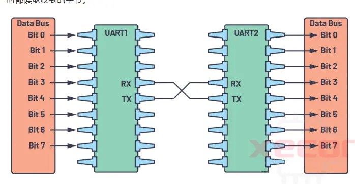
UART communication is an asynchronous serial communication method primarily based on transmitting binary data bits over a data line. A UART communication system consists of a transmitter and a receiver, which exchange data via a data line. The sender converts the data to be sent into parallel signals, which are then converted into serial signals through a driver circuit and transmitted onto the data line. The receiver, on the other hand, uses a receiver circuit to restore the signals from the data line to parallel signals, and then decodes them into the original data bits.

UART communication employs an asynchronous communication method, meaning that the sender and receiver do not need to be active simultaneously. Instead, the start and stop bits are used to indicate the beginning and end of data frames. Specifically, when the sender generates the start bit, it sends one data bit, then waits for the receiver's start bit. If the start bit is received, it proceeds to send the next data bit. If the start bit is not received, the data frame transmission is considered unsuccessful. Similarly, when the receiver generates the stop bit, it sends a checksum bit, then waits for the sender's stop bit. If the stop bit is received, the data frame transmission is considered successful.

Baud Rate of UART
Baud rate represents the number of binary data bits transmitted over a communication line in one unit of time and is typically expressed in bits per second (bps). For example, if the baud rate is 9600 bps, it means that 9600 bits of data can be transmitted in one second.
The baud rate for serial data transmission is generated by the microcontroller's clock system, and it is related to the microcontroller's system clock through the following formula:
Baud Rate = (16 * Clock Frequency) / (32 * Sampling Time) + (1 * Clock Frequency) / (32 * Sampling Time) - (1 * Clock Frequency) / (64 * Sampling Time)
Here, the sampling time represents the time interval between the last start bit and the current start bit. For instance, if the sampling time is 10 nanoseconds, the baud rate would be 9600 bps.
Common baud rates include 2400, 4800, 9600, 19200, 38400, 57600, 115200, and so on, which are all multiples of 2400. Therefore, different baud rates can be generated using a prescaler. Most modern microcontrollers have different clock frequencies, such as 32 MHz, 48 MHz, and 144 MHz. Typically, they have an external clock system that provides a basic clock frequency (e.g., 1 MHz) for the microcontroller's peripheral devices, including UART for generating baud rates.
It's important to note that in practical usage, clock frequencies may be affected by factors such as crystal drift and power noise. Therefore, to ensure the correctness and reliability of data transmission, it is recommended to use an external crystal or clock generator and calibrate and compensate for it when designing a UART communication system.
Stop Bits and Parity
In asynchronous UART communication, stop bits are used to indicate the end of a data frame. Stop bits can be either 1 or 2 bits in length. When using 1 stop bit, an additional time interval is added after each data byte to compensate for clock jitter and other factors. For example, if the baud rate is 9600 bps, the time interval for each byte is 4 milliseconds, so each stop bit's time interval would be 4 ms / 8 = 0.5 ms.
When using 2 stop bits, two additional time intervals are added after each data byte, resulting in a time interval of 4 ms / (8 + 4) = 0.3125 ms per byte. This mode is suitable for scenarios requiring higher data transmission accuracy.
Parity checking is a commonly used error detection method that can identify errors and losses during data transmission. In UART communication, setting a parity bit can enhance the correctness and reliability of data transmission.
It's important to note that parity checking can only detect errors and losses during data transmission but cannot guarantee data integrity and correctness. Therefore, when using UART communication, additional measures should be taken to ensure data transmission correctness and reliability.
Polling and Interrupt-based UART Communication
As mentioned earlier, UART communication involves sending data bit by bit, with each byte of data being broken down into individual bits. After a byte of data is sent to the UART transmitter, it is converted into bits and sent. Once the UART transmitter has completed sending a byte, it enters an idle state, and you can continue sending the next byte. Typically, UART transmitters enter an idle state after sending a byte, and you can wait for this idle state before sending the next byte. This is known as polling-based UART communication.
UART receivers work in a similar manner. After receiving a byte of data and detecting the stop bit, the UART receiver stores the received data byte in the UART data register and generates a received flag. You can continuously poll this flag to retrieve the received byte.
However, in many microcontroller systems, UART communication is not the only task. In such cases, interrupt-based UART communication is more efficient. Most microcontrollers with UART support provide both receive (RX) and transmit (TX) interrupts. During interrupt-based transmission, the UART transmitter is in an idle state after sending a byte, and it generates a TX complete interrupt. In the TX complete interrupt service routine (ISR), you can load the next byte to be transmitted. This process continues until all the bytes to be transmitted are sent.
Similarly, during interrupt-based reception, the UART receiver generates an RX received interrupt when a byte is received. In the RX received interrupt service routine, you can read the received byte from the UART data register. This allows you to efficiently handle UART communication without continuously waiting for UART transmitter or receiver to become idle.
UART Communication with Data Buffers
In many microcontroller systems, UART communication is facilitated using interface functions like UART Read and UART Write. Some advanced microcontrollers even provide callback functions like UART Read Callback and UART Write Callback for data reception and transmission. Typically, microcontrollers with higher data processing capabilities compared to UART communication utilize data buffers to assist in UART communication. Here are some common UART communication methods:
Data Queue (Queue) Communication
This method is suitable for most microcontrollers that support interrupts. When data is transmitted using UART Write, the data is not directly written to the UART transmitter. Instead, it is placed in a circular buffer. In the UART TX complete interrupt service routine, data is read from the circular buffer and sent to the UART transmitter. This process continues until all data in the circular buffer is transmitted. Circular buffers typically have head and tail markers, and as long as these markers are not equal, it indicates that there is data in the buffer. When receiving data using UART Read, data is not directly obtained from the UART receiver. Instead, it is retrieved from the circular buffer. In the UART RX received interrupt service routine, the received byte is placed into the circular buffer. When UART Read is executed, it retrieves data from the circular buffer. This design ensures that the microcontroller program does not need to constantly wait for the UART receiver.
The advantage of this design is that it effectively handles real-time data and prevents data loss. However, if the queue size is not appropriately set, it may lead to data overflow. Therefore, the queue size should be determined based on the specific application requirements.
UART Communication with Hardware FIFO
Many advanced microcontrollers come equipped with hardware FIFO (First-In-First-Out) support for UART communication. In UART communication without hardware FIFO, the microcontroller enters an interrupt function each time a byte is received or transmitted, leading to frequent interrupts and potential interference with the microcontroller's main tasks. Hardware FIFO, however, helps mitigate this issue. For example, a microcontroller's UART FIFO might be set to 16 bytes. This means that when transmitting data, up to 16 bytes can be sent in a single transmission, after which the UART TX complete interrupt is generated. When receiving data, the "half-full" interrupt and "timeout" interrupt are typically used. These interrupts trigger when there are more than 8 bytes in the receive FIFO or when the receive FIFO is not empty, but no new byte has been received within a specified time frame. This design is usually combined with data queue communication and significantly improves transmission efficiency, especially for high baud rate communication.
UART Communication with DMA (Direct Memory Access)
DMA (Direct Memory Access) is a technology that allows a specific area of a computer's memory to be directly mapped to memory address space, enabling direct access to memory and other peripherals. In UART communication with DMA, when data is received by the UART, it is directly written into a memory area controlled by DMA. This action triggers an interrupt. In the interrupt service routine, data can be retrieved from the DMA-controlled memory area, processed as needed, and then sent via UART.
DMA-based UART transmission is particularly helpful for continuous transmission of multiple data streams, such as those involving UART Read Callback and UART Write Callback callback functions. When transmitting multiple data streams consecutively, each data stream can be placed in different buffers within the microcontroller. DMA is then used to directly point to the buffer's address, and when DMA completes transmission, a UART Write Callback is generated. In the UART Write Callback, the DMA is pointed to the next buffer's address. This process continues until all required data has been transmitted. When receiving data, a receive buffer can also be pre-allocated. Data transferred by DMA is placed in the receive buffer, and once the buffer is full, an UART Read Callback can be generated. DMA is then directed to the next receive buffer, allowing the main microcontroller program to handle the content of the full data buffer while new data continues to be received.
This article has provided an in-depth explanation of UART communication, covering its basic principles, baud rate calculation, operating modes, and common usage scenarios. Mastering UART communication technology can greatly facilitate the design and implementation of microcontroller control systems.
More Application-Related Electronic Components
PI3USB10MZEEX
Dual 2:1 Analog Multiplexer with 12-Pin TDFN EP
PJS008-2003-0
Memory Card Connectors MicroSD Crd Conn SMT Revrs Mnt Push-Push
LFCN-80+
Signal Conditioning LOW PASS FLTR / SURF MT / RoHS

KC2520B27.0000C10E00
Oscillator XO 27MHz ±50ppm 15pF CMOS 55% 1.8V/2.5V/3.3V 4-Pin Mini-CSMD T/R
HMC336MS8GE
RF Switch ICs SPDT Positive Control Swt , DC - 6 GHz
CPFC74NP-PS02H2A20
Common Mode Chokes Dual 200Ohm 20MHz to 300MHz 2A 0.12Ohm DCR SMD
CHS-01TA1
DIP Switches / SIP Switches smd slide 1 pos., J hook, non-washable without seal tape
BKP1005EM221-T
Ferrite Beads Multi-Layer Power 220Ohm 25% 100MHz 1A 0.15Ohm DCR 0402 T/R
READ ALSO
-
Rapidly Establishing a Local LoRaWAN Network Using LoRaWAN Gateways Date: 26/09/2023
LoRa modulation is a low-power, wide-area network communication technology, based on spread spectrum technology, developed by Semtech. LoRaWAN is a set of communication protocols and system architecture designed for long-range communication networks using LoRa technology. It functions as the Media Access Control (MAC) layer protocol.
-
Comprehensive Explanation of the Modbus Communication Protocol Date: 26/09/2023
The Modbus protocol is a universal language used in electronic controllers, facilitating communication between controllers, networking via Ethernet, and interaction with other devices. It has become a widely adopted industrial standard, enabling control devices from different manufacturers to connect into industrial networks for centralized monitoring.
-
MES System Collects PLC Data via OPC Intelligent Gateway Date: 25/09/2023
OPC is a common communication protocol in the industrial control field, used in devices such as PLCs, DCS, SCADA, and more. It enables interconnection and communication between industrial automation devices and can be integrated with other factory systems to enhance efficiency. Through the use of the物通博联 (Wu Tong Bolian) OPC intelligent gateway, MES (Manufacturing Execution System) can obtain real-time PLC data, enabling functions such as remote monitoring, remote control, and equipment management, thus assisting enterprises in creating a digital factory and information-based management.