How to Choose BWP in 5G Networks?
Once a user equipment (UE) is configured with multiple BWP (Bandwidth Parts), the network (RAN) has the authority to instruct the UE to perform BWP switching. This is done in the following ways:
-
Through Physical Downlink Control Channel (PDCCH) carrying Downlink Control Information (DCI).
-
Using DCI Format 1_1 for downlink allocation and DCI Format 0_1 for uplink grant, both of which contain 1 or 2 bits BWP indication variables.
When there are two or more BWPs integrated into the system, 2-bit indicators can effectively serve this purpose.
A third BWP switching mechanism is triggered automatically to switch back to the default BWP when the BWP becomes inactive due to a BWP Inactivity Timer timeout.
The BWP Inactivity Timer value ranges from 2 to 2560 milliseconds.
The maximum value of this timer is related to the Discontinuous Reception (DRX) Inactivity Timer.
BWP Switching
In 5G, UE performs BWP switching based on DCI and Timer, with the following delay requirements between the network and UE for transmission (downlink) and reception (uplink):
BWP switching based on DCI introduces delays on both the network and UE sides.
UE must complete the downlink (DL) or uplink (UL) switch within the specified BWP switch delay time.

Table 1. BWP Switching Time Limits for DCI and Timers
Delay Levels
As shown in Figure 1, there are two levels: Type 1 and Type 2, where:
-
BWP Switching Delay based on DCI (BWPswitchDelay): It is defined as the slot difference between the DL slot of the switching request and the first slot on the new BWP used for PDSCH reception (DL) or PUSCH transmission (UL).
-
UL/DL Signal Switching Delay: During BWP switching based on DCI in the serving cell, the UE is not obligated to transmit UL signals or receive DL signals during the BWP switch delay.
SCS and BWP Switching Impact
The BWP switching delay in 5G networks is related to Subcarrier Spacing (SCS). When switching across different BWP with varying SCS values, the delay follows the rules shown in Figure 1, following the requirements of the smaller SCS.
Bandwidth Adaptation
Bandwidth Adaptation (BA) is an innovative capability introduced for User Equipment (UE) to independently adjust its receiving and transmitting bandwidth without being constrained by the total cell bandwidth. This multifunctional feature allows UE to conserve energy while dynamically adapting to fluctuating data demands. The responsiveness of bandwidth adjustments becomes evident in various scenarios, with advantages including:
-
Efficient Utilization: BA enables UE to use narrower bandwidths, making it well-suited for tasks like monitoring control channels or receiving moderate data loads. This strategic move optimizes power consumption.
-
Seamless Expansion: In scenarios requiring data-intensive transmission, UE seamlessly transitions to wider or full bandwidths to meet evolving requirements.
-
Frequency Domain Agility: BA introduces frequency domain adaptability, allowing UE to adapt to changes in its location and customizable subcarrier spacing. This adaptability effectively caters to diverse service requirements.
-
BWP Configuration: Implementing BA requires configuring Bandwidth Parts (BWPs) that serve as adjustable bandwidth segments.
-
Dynamic Activation: Active BWPs are explicitly communicated to UE from the configured array of BWPs, enabling real-time adaptability.

Figure 2. Example of BA Configuration
As an application scenario example, consider a scenario with three different BWPs configured, where the Primary Cell (PCell) is configured with uplink (UL) and downlink (DL) BWPs to seamlessly accommodate BA. In the context of Carrier Aggregation (CA) involving Secondary Cells (SCell), at least a DL BWP is configured. However, the presence of an UL BWP in SCell depends on the specific configuration.
More Application-Related Electronic Components
PJS008-2003-0
Memory Card Connectors MicroSD Crd Conn SMT Revrs Mnt Push-Push
LFCN-80+
Signal Conditioning LOW PASS FLTR / SURF MT / RoHS
HMC336MS8GE
RF Switch ICs SPDT Positive Control Swt , DC - 6 GHz
CPFC74NP-PS02H2A20
Common Mode Chokes Dual 200Ohm 20MHz to 300MHz 2A 0.12Ohm DCR SMD
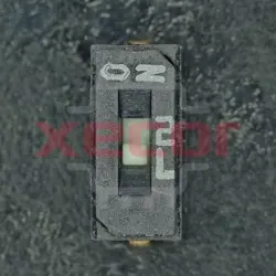
CHS-01TA1
DIP Switches / SIP Switches smd slide 1 pos., J hook, non-washable without seal tape
BKP1005EM221-T
Ferrite Beads Multi-Layer Power 220Ohm 25% 100MHz 1A 0.15Ohm DCR 0402 T/R
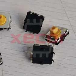
B3W-4055
Tactile Switches 12x12mm NoGroundTerm Prjctd 7.3mmH 350OF
B3F-4050
Switch Tactile N.O. SPST Projected Plunger PC Pins 0.05A 24VDC 1.27N Thru-Hole Bag
READ ALSO
-
Rapidly Establishing a Local LoRaWAN Network Using LoRaWAN Gateways Date: 26/09/2023
LoRa modulation is a low-power, wide-area network communication technology, based on spread spectrum technology, developed by Semtech. LoRaWAN is a set of communication protocols and system architecture designed for long-range communication networks using LoRa technology. It functions as the Media Access Control (MAC) layer protocol.
-
Comprehensive Explanation of the Modbus Communication Protocol Date: 26/09/2023
The Modbus protocol is a universal language used in electronic controllers, facilitating communication between controllers, networking via Ethernet, and interaction with other devices. It has become a widely adopted industrial standard, enabling control devices from different manufacturers to connect into industrial networks for centralized monitoring.
-
MES System Collects PLC Data via OPC Intelligent Gateway Date: 25/09/2023
OPC is a common communication protocol in the industrial control field, used in devices such as PLCs, DCS, SCADA, and more. It enables interconnection and communication between industrial automation devices and can be integrated with other factory systems to enhance efficiency. Through the use of the物通博联 (Wu Tong Bolian) OPC intelligent gateway, MES (Manufacturing Execution System) can obtain real-time PLC data, enabling functions such as remote monitoring, remote control, and equipment management, thus assisting enterprises in creating a digital factory and information-based management.