Understanding the TEENSY 3.6 Development Board Pinout
 Prof. David Reynolds
Published:April 24, 2024
The TEENSY development boards have evolved over the years to meet the demands of the maker and DIY communities. The TEENSY 3.6 is part of this evolution(other boards such as Teensy LC, Teensy 3.2, and Teensy 3.5.), offering more features, improved performance, and enhanced capabilities compared to its predecessors. The significance of TEENSY boards lies in their ability to provide a compact and cost-effective platform for developing innovative projects. Understanding the pinout of the TEENSY 3.6 is essential for correctly connecting external components and peripherals. The pinout layout of the TEENSY 3.6 is organized in a specific manner to facilitate easy identification and connection. Each pin has a unique function, such as digital input/output, analog input, PWM output, or communication interface. Understanding these pin functions is crucial for designing and implementing projects effectively. This article provides a comprehensive guide to the TEENSY 3.6 pinout, covering its pin diagram, pin configuration, functions, and applications in detail. Whether you're a beginner looking to learn about development boards or an experienced developer seeking to harness the capabilities of TEENSY 3.6, this article will help you understand how to use Teensy 3.6.
Overview of TEENSY 3.6 Development Board
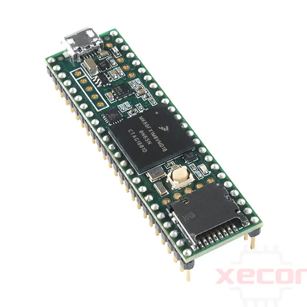
The Teensy USB Development Board is a comprehensive USB-based microcontroller development system. The Teensy 3.6 version is equipped with a 32-bit 180 MHz ARM Cortex-M4 processor with a floating-point unit, allowing programming using the Arduino software. It includes a bootloader for easy programming through its high-speed onboard USB port. The board is designed to provide ARM Cortex processing power in a breadboard-friendly package for hobbyist use.
One of its key features is the built-in programmer and debugger, eliminating the need for additional components to program and use the TEENSY 3.6 development board. Importantly, it is fully compatible with the Arduino IDE, ensuring that most programs written for the Arduino Uno can be used on the Teensy development board without any modifications. The TEENSY 3.6 development board is ideal for various electronics projects, from robotics to IoT applications.
Other development boards available in the market include Arduino, STM32, ESP12, ESP32, Raspberry Pi, and ESP8266.
TEENSY 3.6 Development Board Pinout
Teensy 3.6 Pin Diagram
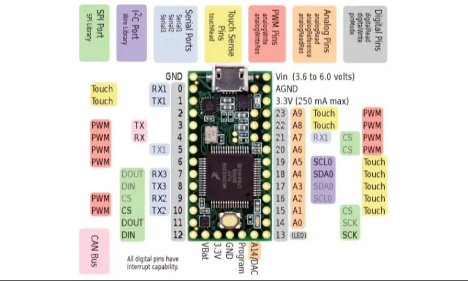
The following figure displays the pinout diagram of the TEENSY 3.6 Development Board. It features 33 pins and offers advanced functionalities not found in Arduino, including DMA memory channels, high-resolution ADCs, CAN communication, and a digital audio interface.
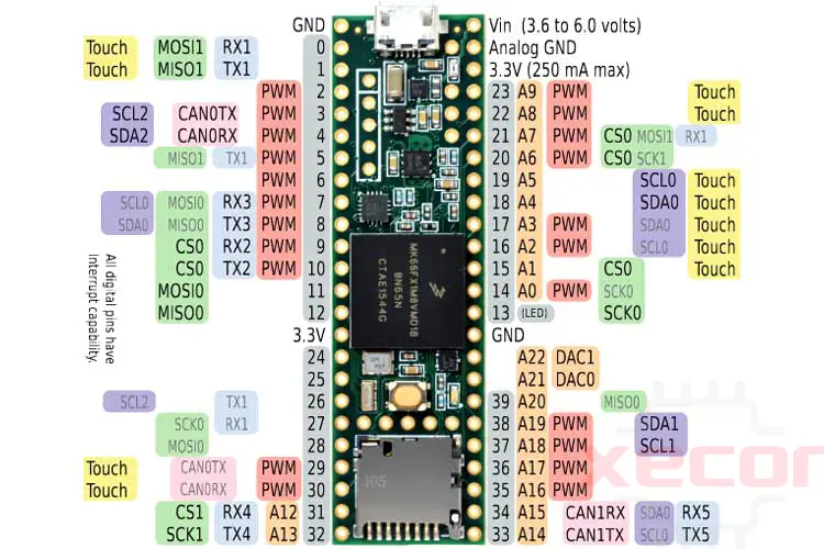
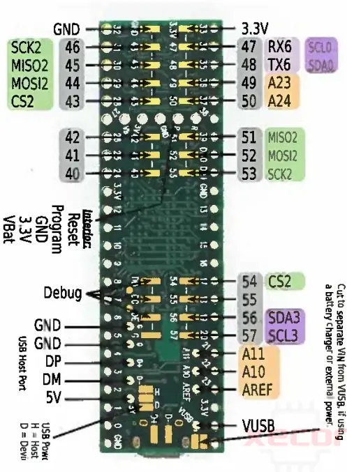
Additionally, this board has additional pin assignments on the backside. The diagram illustrates the pinout of the backside layout.
Teensy 3.6 Pin Configuration
|
Pin Category |
Pin Name |
Details |
|
Power |
VIN, 3.3V, Analog GND, GND |
VIN – Supply voltage pin when using an external power source (3.6V to 6.0V) 3.3V – Regulated output voltage from the onboard regulator (250mA max.) Analog GND – Acts as GND for the ADC and DAC, can be connected to GND GND – Ground pins |
|
Analog Pins |
A0 – A22 |
Pins A0 – A22 can act as analog inputs with 13-bit resolution Pins A21 and A22 act as DACs with 12-bit resolution |
|
Input/output pins |
D0 – D61 |
42 I/O pins breadboard friendly |
|
Serial |
· TX1, RX1 · TX2, RX2 · TX3, RX3 · TX4, RX4 |
2 serial ports have FIFO capability Fast baud rates |
|
External interrupts |
D0 – D61 |
All digital pins have interrupt capability |
|
PWM |
· D2 – D10 · D29 –D30 · D14 · D16 – D17 · D20 – D23 · D35 – D38 |
22 PWM pins total |
|
SPI |
· MISO0, MOSI0, SCK0, CS0 · MISO1, MOSI1, SCK1, CS0 |
2 SPI ports with FIFO |
|
Inbuilt LED |
D13 |
LED to act as a general-purpose GPIO indicator |
|
I2C |
· SCL0, SDA0 · SCL1, SDA1 · SCL2, SDA2 |
Inter-Integrated Circuit communication ports |
|
CAN |
· CAN0TX, CAN0RX · CAN1RX, CAN1TX |
CAN bus ports |
|
Touch sensing |
· D0 – D1 · D29 – D30 · D15 – D19 · D22 – D23 |
Can be used for capacitive touch sensing |
Serial Communication Pins
The TEENSY 3.6 Development Board features six serial communication channels accessible through the following GPIO pins:
- GPIO0: RX1
- GPIO1: TX1
- GPIO9: RX2
- GPIO10: TX2
- GPIO7: RX3
- GPIO8: TX3
- GPIO31: RX4
- GPIO32: TX4
- GPIO34: RX5
- GPIO33: TX5
- GPIO47: RX6
- GPIO48: TX6
The signals at these pins operate at the TTL level. Two serial ports support high baud rates and are equipped with FIFO. The transmit pins use interrupts, while the receive pins have buffers to prevent waiting for short messages. These ports facilitate data transmission and reception using the UART protocol.
PWM pins
The board offers a total of 22 PWM pins, namely D2 to D10, D29, D30, D14, D16, D17, D20 to D23, and D35 to D38.
SPI Ports
It features two SPI communication ports:
- SPI Port 1: MISO0, MOSI0, SCK0
- SPI Port 2: MISO1, MOSI1, SCK1
Power pins
The TEENSY 3.6 Development Board includes the following power pins:
- VIN: This pin is used for voltage supply from an external source, accommodating a voltage range of 3.6V to 6V.
- 3.3V: This pin features an onboard voltage regulator providing a regulated output voltage of 3.3V. The maximum current for this regulator is 250mA.
- Analog GND: Connect this pin to the main ground. It serves as the ground pin for analog-to-digital and digital-to-analog converters.
- GND: Connect this pin to the circuit ground.
- 5V: This board also provides a 5-volt source, which is useful for powering sensors that require a 5-volt power supply. You can access the 5-volt source from the backside of the board.
Analog Pins
The TEENSY 3.6 Development Board has 25 analog inputs connected to two analog-to-digital converters with a 13-bit resolution and two analog outputs with a 12-bit resolution.
- GPIO_D14: Channel_A0
- GPIO_D15: Channel_A1
- GPIO_D16: Channel_A2
- GPIO_D17: Channel_A3
- GPIO_D18: Channel_A4
- GPIO_D19: Channel_A5
- GPIO_D20: Channel_A6
- GPIO_D21: Channel_A7
- GPIO_D22: Channel_A8
- GPIO_D23: Channel_A9
- GPIO_X: Channel_A10 (Connection available on the backside of the Teensy 3.6)
- GPIO_X: Channel_A11 (Connection available on the backside of the Teensy 3.6)
- GPIO_D31: Channel_A12
- GPIO_D32: Channel_A13
- GPIO_D33: Channel_A14
- GPIO_D34: Channel_A15
- GPIO_D35: Channel_A16
- GPIO_D36: Channel_A17
- GPIO_D37: Channel_A18
- GPIO_D38: Channel_A19
- GPIO_D39: Channel_A20
- GPIO_D40: Channel_A21
- GPIO_D42: Channel_A22
- GPIO_D49: Channel_A23
- GPIO_D50: Channel_A24
I/O pins
The board features 62 digital input-output pins, all of which have the on-change interrupt feature. However, only 42 of these pins are breadboard-friendly. You can access the other GPIO pins from the backside of the TEENSY 3.6 board.
I2C Protocol pins
The TEENSY 3.6 Development Board features four ports for I2C communication, with the following assignments:
- GPIO_D19: SCL0
- GPIO_D18: SDA0
- GPIO_D37: SCL1
- GPIO_D38: SDA1
- GPIO_D3: SCL2
- GPIO_D4: SDA2
- GPIO_D57: SCL3
- GPIO_D56: SDA3
Touch Sensing Outputs
Eleven pins are dedicated to capacitive touch sensing: D0, D1, D29, D30, D15 to D19, D22, and D23.
DAC Pins
The board features two DAC modules that can be utilized as analog output pins, each with a 12-bit resolution. The associated pins on the development board are:
- GPIO_D40: DAC0
- GPIO_D41: DAC1
Status LED
Pin 13 is an LED pin that includes an onboard LED.
Special Functions of Pins
Input/Output:
The TEENSY 3.6 boasts 62 GPIO pins, each with a current sink/source capability of 25mA. These pins can also have pull-up resistors enabled.
Additionally, most pins offer extra functionality:
- Serial ports for receiving and transmitting data using the UART protocol
- I2C ports for two-wire communication using the IIC protocol
- SPI for fast serial communication
- PWM for outputting an 8-bit pulse width modulated square wave
- Pin 13 features a built-in LED.
The diagram above illustrates these special functions and their respective pins on the TEENSY 3.6.
TEENSY 3.6 Features
- 1M Flash Memory
- 256KB SRAM
- 4KB EEPROM
- MK66FX1M0VMD18 microcontroller
- USB port with a full speed of 12 Mbit/sec
- 4-bit SDIO port for SD card
- Ethernet MAC with a speed of 100 Mbit/sec
- 62 Input/output pins with a source/sink current of 25mA
- 25 Analog Inputs
- 2 Analog Outputs (DACs) with 12-bit resolution
- 14 Hardware timers
- 22 PWM Outputs
- 3 ports for the C interface
- 3 ports for SPI Interface, one with FIFO
- Six serial ports with fast baud rates
- S audio port with four-channel digital audio input and output
- Real-time clock with a speed of 180MHz
- Cryptographic acceleration
- CRC Computation unit
- Random number generator
TEENSY 3.6 Specifications
|
Type |
Value |
|
Microcontroller |
MK66FX1M0VMD18 |
|
Operating voltage |
3.3V |
|
Recommended input voltage for VIN pin |
3.6V to 6.0V |
|
Analog inputs |
25 |
|
Digital I/O pins |
62 |
|
DC source/sink from I/O pins |
25mA |
|
Flash memory |
1M |
|
SRAM |
256KB |
|
EEPROM |
4KB |
|
Frequency (clock speed) |
180MHz |
|
Communication |
I2C, SPI, UART, CAN, USB |
How to Power Teensy 3.6 Development Board
You can power your Teensy 3.6 development board in three ways:
- Use the built-in USB micro connector.
- This method is recommended. It involves supplying a voltage of 3.6V to 6V from an external supply, such as a 5V regulator.
- Supply 3.3V directly to the 3.3V pin. However, this method is not recommended because the supply line is directly connected to the microcontroller, so any spikes or ripples might cause damage.
How to Program Teensy 3.6
Programming the Teensy 3.6 is straightforward and can be done using any C editor or Arduino software, which is recommended for beginners due to its ease of use.
To begin, download the Arduino software from the following link:
Once downloaded, connect the Teensy 3.6 to your computer via the USB micro port.
Uploading Your First Program:
- Select the correct board (Teensy 3.6) from the Tools > Boards menu.
- Choose the correct COM port under Tools > Ports.
Since the built-in LED is on pin 13, similar to Arduino boards, you can use the basic blink sketch. Here is the code:
void setup() {
pinMode(13, OUTPUT);
}
void loop() {
digitalWrite(13, HIGH);
delay(1000);
digitalWrite(13, LOW);
delay(1000);
}
TEENSY 3.6 Development Board Application
Rapid Prototyping:
- The TEENSY 3.6 development board is widely used for rapid prototyping of electronic systems and projects.
- Its fast processor and extensive peripheral support make it ideal for quickly implementing and testing new ideas and concepts.
Hardware-Accelerated Cryptography:
- The TEENSY 3.6 development board features hardware-accelerated cryptography support, making it suitable for applications requiring secure communication and data encryption.
- Its cryptographic capabilities enable developers to implement secure communication protocols and data encryption algorithms with ease.
Robotics:
- In robotics applications, the TEENSY 3.6 development board is used for controlling and coordinating various robotic systems.
- Its high processing power and real-time capabilities make it ideal for tasks such as processing sensor data, motor control, and decision-making in robotics.
LED Strips:
- LED strips often use the TEENSY 3.6 development board due to its high processing power and direct memory access (DMA) capabilities.
- The board can efficiently control and manage LED strips, allowing for complex lighting effects and patterns to be easily implemented.
GPS Receivers and ESP WiFi Modules:
- The TEENSY 3.6 development board is commonly used with GPS receivers and ESP WiFi modules for various applications.
- Its compatibility with these modules allows for the development of location-based services, IoT devices, and other wireless communication systems.
Teensy 3.6 Development Board Datasheet
Download Teensy 3.6 Development Board Datasheet.
Teensy 3.6 vs. Arduino Uno
| Feature | Teensy 3.6 | Arduino Uno |
| Processor | MK66FX1M0VMD18(ARM Cortex-M4 32-bit) | Atmega328P 8-bit |
| CPU speed | 180MHz | 16MHz |
| Flash Memory | 1 MB | 32 KB |
| Operating/input voltage | 3.3V | 5V |
| Analog pins | 25 | 8 |
| Digital IO/PWM | 62 | 14 |
| EEPROM/SRAM(KB) | 4/256 | 1/2 |
| USB Connector | Micro | Mini |
| USB Ports | 1 | 1 |
| UART | 4 | 1 |
| SPI | 2 | 1 |
| I2C | 3 | 1 |
| Price | Typically higher | Typically lower |
The Teensy 3.6 offers more advanced capabilities, such as a faster processor, more memory, and additional I/O pins, making it suitable for more complex projects. However, the Arduino Uno is more cost-effective and may be more suitable for simpler projects or beginners.
Teensy 3.6 vs. Teensy 3.2
| Feature | Teensy 3.6 | Teensy 3.2 |
| Processor | MK66FX1M0VMD18 | MK20DX256 |
| Architecture | ARM Cortex-M4 | ARM Cortex-M4 |
| CPU speed | 180MHz | 72MHz |
| Flash Memory | 1 MB | 256 KB |
| Operating/input voltage | 3.3V | 3.3V |
| RAM | 256 KB | 64 KB |
| Analog pins | 25 | 21 |
| Digital IO/PWM | 62 | 34 |
| EEPROM/SRAM(KB) | 4/256 | 2/64 |
| USB Connector | Micro | Micro |
| PWM Channels | 12 | 8 |
| UART | 4 | 3 |
| SPI | 2 | 1 |
| I2C | 3 | 1 |
| Price | Typically higher | Typically lower |
The Teensy 3.6 offers higher performance with a faster core speed, more flash memory, and more I/O pins compared to the Teensy 3.2. However, the Teensy 3.2 is more cost-effective and may be suitable for simpler projects that do not require the higher specifications of the Teensy 3.6.
Conclusion
In summary, the Teensy 3.6 development board is a powerful and versatile platform for electronics projects. With its high clock speed, ample memory, and numerous pins, it can handle a wide range of tasks. The compatibility with the Arduino IDE makes it easy to use for beginners and experienced developers alike. Its compact size and low power consumption make it suitable for portable and battery-powered projects. Overall, the Teensy 3.6 is a reliable and efficient development board that offers great performance for a variety of applications.
Read More
- STM32H7 Microcontroller Features, Development, Datasheet
- Understanding the TEENSY 3.2 Development Board Pinout
- ESP32 vs. ESP8266: How to Choose the Right Microcontrollers
- STM32F103C6T6 Datasheet, Pinout, Schematic, Programming, and Specs
- STM32F103C8T6 Blue Pill Development Board Pinout, Specs, Programming & Datasheet
Previous:
FAQ
-
What is the maximum clock speed of the Teensy 3.6?
180 MHz.
-
What is the recommended power supply voltage for the Teensy 3.6?
3.6V to 6.0V.
-
How do I choose the right Teensy 3.6 pins for my project?
Choosing the right pins on the TEENSY 3.6 Development Board depends on the requirements of your project. Consider the following factors:
- Functionality: Determine the purpose of each pin (e.g., digital I/O, analog input, communication interface).
- Compatibility: Ensure the selected pins are compatible with the sensors, actuators, or peripherals you plan to use.
- Availability: Check the availability of pins based on the other components connected to the board.
- Special features: Consider using special function pins (e.g., PWM, interrupt) for specific project requirements.
-
How many analog pins does the Teensy 3.6 have?
The Teensy 3.6 has 21 analog input pins.
-
Can I use Teensy 3.6 with Arduino shields?
Yes, the TEENSY 3.6 Development Board is compatible with most Arduino shields. However, due to differences in pinout and voltage levels, some shields may require modification or additional circuitry to work properly with TEENSY 3.6. It's recommended that you check the shield's compatibility with the TEENSY 3.6 before use.
Still, need help? Contact Us: [email protected]