
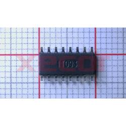
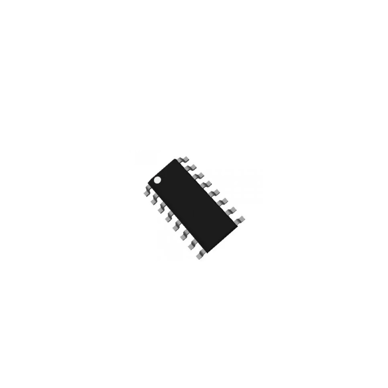
ULN2003AIPWR
50 volt, 7-channel Darlington transistor array
| Quantity | Unit Price(USD) | Ext. Price |
|---|---|---|
| 1 | $0.358 | $0.36 |
| 10 | $0.287 | $2.87 |
| 30 | $0.258 | $7.74 |
| 100 | $0.221 | $22.10 |
| 500 | $0.185 | $92.50 |
| 1000 | $0.175 | $175.00 |
Inventory:7,450
- 90-day after-sales guarantee
- 365 Days Quality Guarantee
- Genuine Product Guarantee
- 7*24 hours service quarantee
-
Part Number : ULN2003AIPWR
-
Package/Case : TSSOP (PW)-16
-
Brands : TI
-
Components Categories : Power Distribution Switches, Load Drivers
-
Datesheet : ULN2003AIPWR DataSheet (PDF)
The ULN2003AIPWR is a high-voltage, high-current Darlington transistor array IC commonly used for driving a wide range of inductive loads such as relays, solenoids, stepper motors, and LED displays. It features seven Darlington pairs with common emitters and clamp diodes for inductive load protection, making it a versatile and robust driver solution. (Note: The pin configuration below is a general representation. Refer to the specific datasheet for precise details.) Include a circuit diagram illustrating how to use the ULN2003AIPWR to drive inductive loads efficiently and safely. Note: For detailed technical specifications, please refer to the ULN2003AIPWR datasheet. Functionality The ULN2003AIPWR is designed to efficiently drive inductive loads by providing high-current amplification and protection against voltage spikes generated by inductive components. It simplifies the interfacing of microcontrollers and digital circuits with inductive loads. Usage Guide Q: Can the ULN2003AIPWR drive stepper motors? Q: Is the ULN2003AIPWR suitable for driving high-power LEDs? For similar functionalities, consider these alternatives to the ULN2003AIPWR:Overview of ULN2003AIPWR
Pinout
Circuit Diagram
Key Features
Application
Frequently Asked Questions
A: Yes, the ULN2003AIPWR is commonly used as a stepper motor driver due to its high-current Darlington pairs suitable for driving the motor windings efficiently.
A: Yes, the ULN2003AIPWR can be used to drive high-power LEDs by providing the necessary current and voltage levels for proper illumination.Equivalent
Specifications
The followings are basic parameters of the part selected concerning the characteristics of the part and categories it belongs to.
| Drivers per package | 7 | Switching voltage (max) (V) | 50 |
| Output voltage (max) (V) | 50 | Peak output current (A) | 0.5 |
| Delay time (typ) (ns) | 250 | Input compatibility | CMOS, TTL |
| Vol at lowest spec current (typ) (mV) | 900 | Iout/ch (max) (mA) | 500 |
| Iout_off (typ) (µA) | 50 | Rating | Catalog |
| Operating temperature range (°C) | -40 to 105 | FET | Internal |
| Imax (A) | 0.5 | Device type | Low-side switches |
| Function | Automotive load dump compatibility, Inductive load compatibility |
Warranty & Returns
Warranty, Returns, and Additional Information
-
QA & Return Policy
Parts Quality Guarantee: 365 days
Returns for refund: within 90 days
Returns for Exchange: within 90 days
-
Shipping and Package
Shipping:For example, FedEx, SF, UPS, or DHL.UPS, or DHL.
Parts Packaging Guarantee: Featuring 100% ESD anti-static protection, our packaging incorporates high toughness and superior buffering capabilities.
-
Payment
For example, channels like VISA, MasterCard, UnionPay, Western Union, PayPal, and more.
If you have specific payment channel preferences or requirements, please get in touch with our sales team for assistance.
Similar Product
ULN2003ADR
500mA current capacity with 50V voltage rating
ULQ2004AN
Trans Darlington NPN 50V 0.5A 16-Pin PDIP Tube
ULN2003APWR
Darlington Transistors Hi-Vltg Hi-Crnt Darl Transistor Arrays
ULN2003AIDR
Trans Darlington NPN 50V 0.5A 16-Pin SOIC T/R
ULN2003ADE4
Darlington Transistors Darlington
ULQ2004ADR
Darlington Transistors Hi V & A Darlington
TPS54332DDAR
Wide Input Voltage Range from 3.5V to 28V
TPS54620RHLR
Synchronous SWIFT™